News And Events

Common Causes of Industrial Connector Failure

Views: 348 Author: Site Editor Publish Time: 2026-05-29 Origin: Site

As an automation engineer or MRO technician, you know a single compromised seal on a waterproof industrial connector can stall an entire line in seconds. Grounded in IEC 60529 standards, this guide breaks down common failure modes across circular architectures, helping you diagnose root causes and prevent costly unplanned downtime.
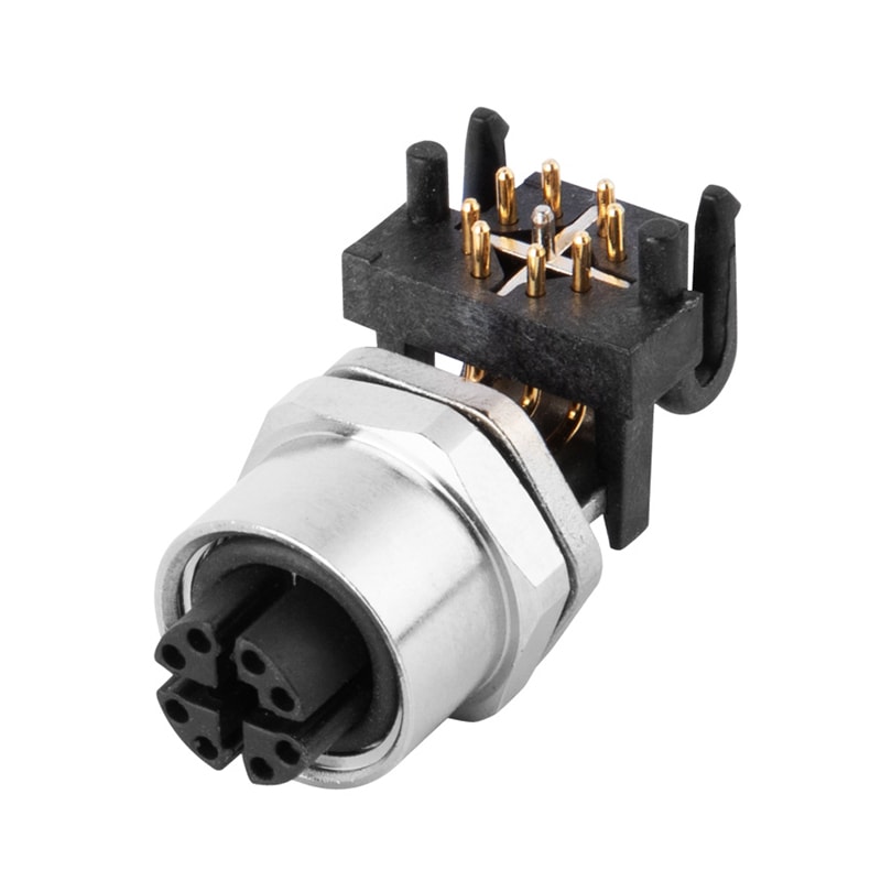
Failure one: Moisture & Fluid Ingress (IP Sealing Breakdown)

When a waterproof seal fails, moisture ingress drops insulation resistance below 50 MΩ, triggering short circuits and galvanic corrosion. On a live plant floor, this path of least resistance often causes catastrophic electrical arcing that destroys the internal connector carrier.

Root Causes of Sealing Loss

  • IP Rating Misinterpretation: Under IEC 60529, IP67 only covers temporary immersion (1 meter for 30 minutes). Deploying it in deep wells or permanent underwater applications causes capillary leakage under continuous hydrostatic pressure.
  • Seal Degradation: Standard O-rings swell or crack when exposed to thermal cycles, caustic washdown detergents, or synthetic cutting oils.
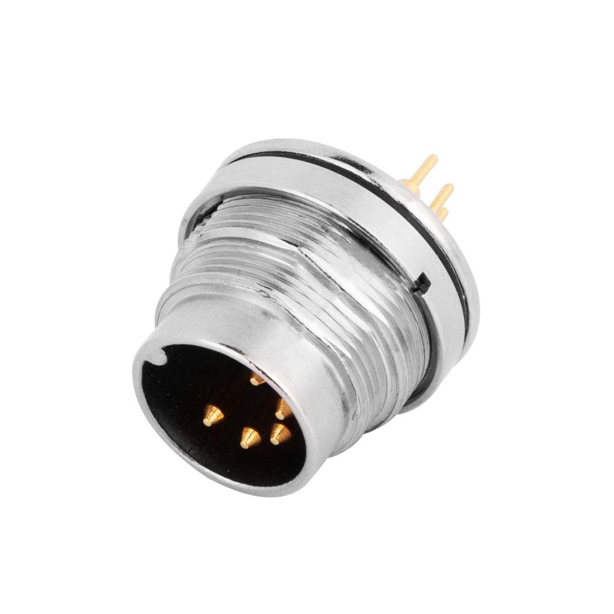
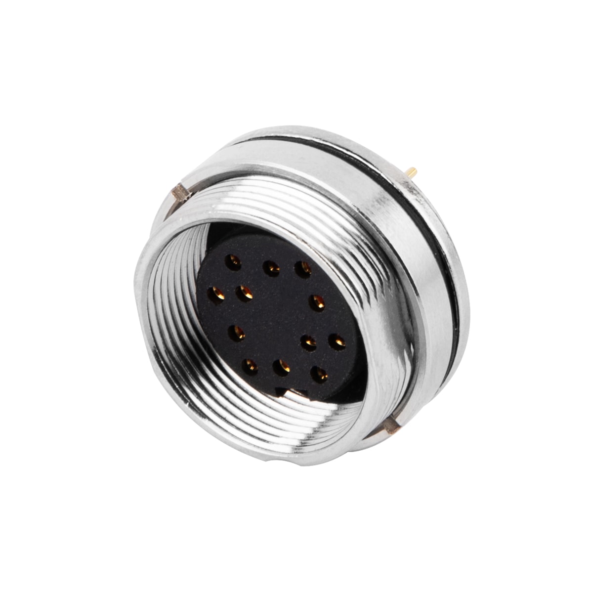
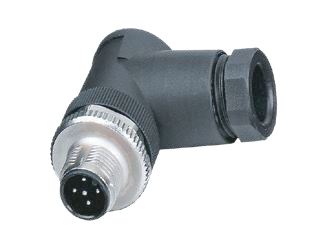
  • Improper Installation Torque: Hand-tightening circular couplings like M12 threads without the required 0.5 to 0.6 Nm torque leaves minute gaps, dropping protection to IP40 within hours.
  • Cable Capillary Action: Damaged cable jackets allow temperature shifts to pull fluid internally along copper strands directly into the sealed contacts.

Material-Level Prevention

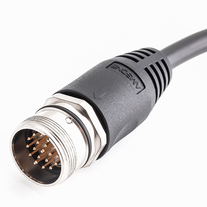
To eliminate field assembly risks, transition to factory-overmolded industrial cables with solid PUR or PVC barriers. For harsh chemistries, specify premium fluororubber (FKM) O-rings to maintain elasticity from -40°C to +200°C, extending component life from months to years.

Failure Two: Vibrational Stress & Mechanical Loosening

Continuous machine vibration poses a severe threat to your network. Over time, high-frequency kinetic energy transfers directly into insecure couplings, turning a stable automated connection into a primary source of intermittent data dropouts and unexpected system downtime.

Symptoms of Vibrational Wear

  • Fretting Corrosion: Constant micro-movements at the contact interface scrape away protective plating. This exposes base metals to oxidation, spiking contact resistance and causing erratic signal jitter across your sensor lines.
  • Coupling Back-Off: Without physical locking mechanisms, standard threaded joints gradually back out. This small structural separation breaks the internal gas-tight seal long before the plug physically detaches from the socket.
  • Termination Fatigue: Unsecured cable weight shifts dynamic forces onto internal connection points. Continuous pulling and twisting eventually snap copper filaments right at the internal solder or crimp joints.

Mitigation Strategies

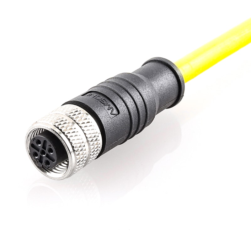
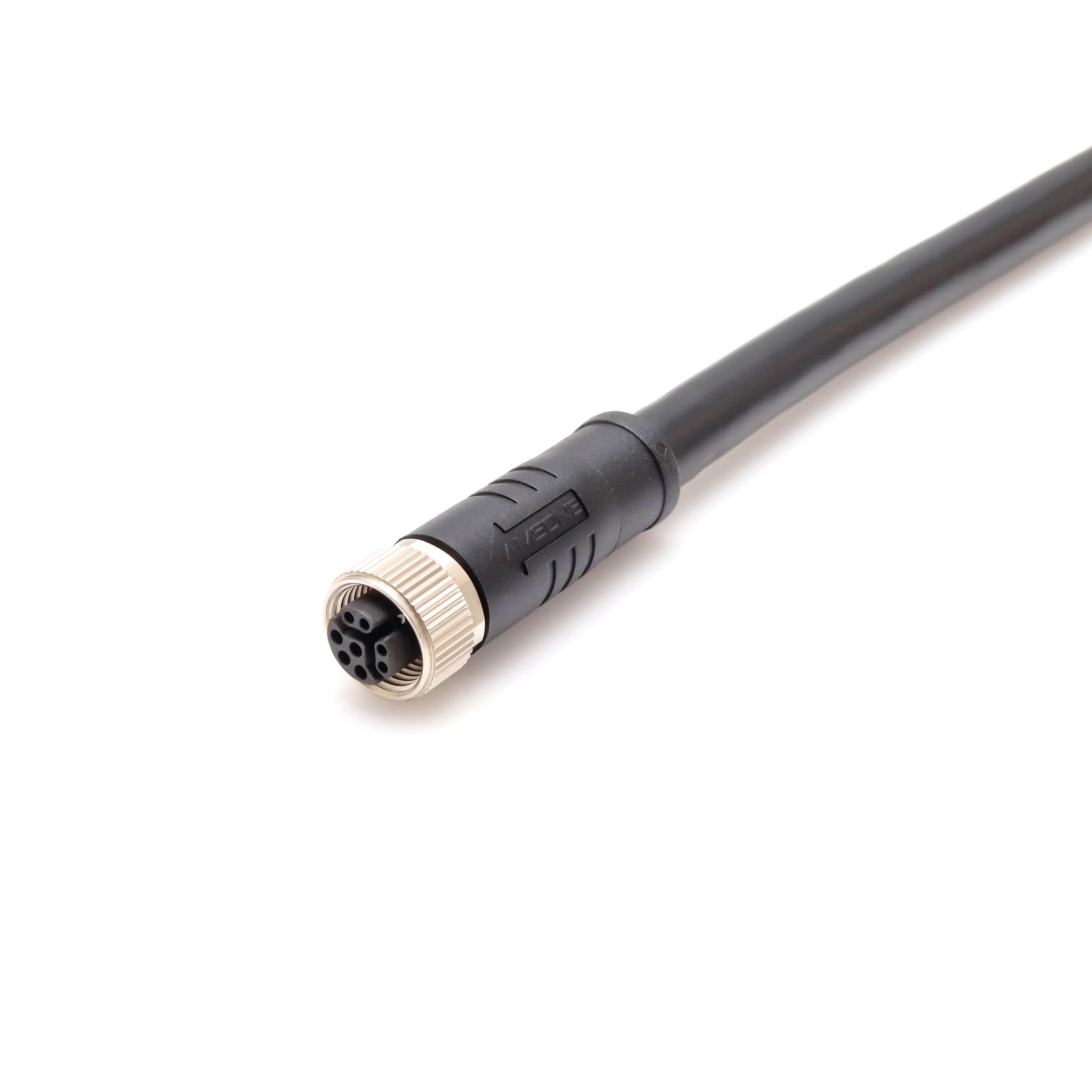
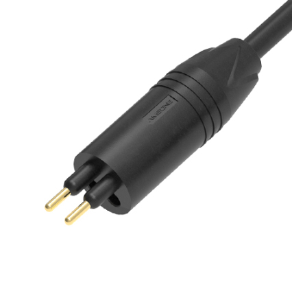
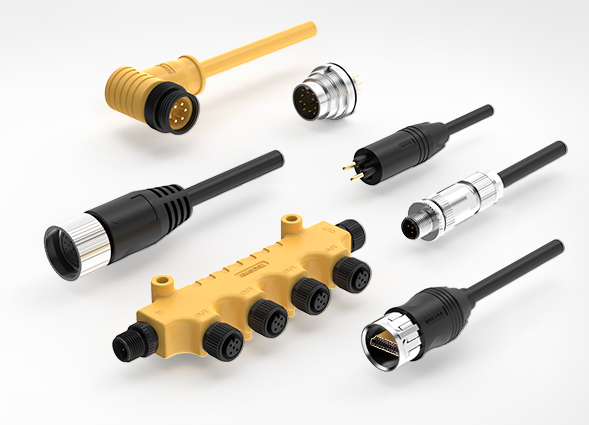
Defeating vibration requires hardware engineered for dynamic motion. Utilizing factory-overmolded circular connectors with integrated strain relief boots ensures that bending stresses are distributed away from fragile termination zones, protecting your automated links.
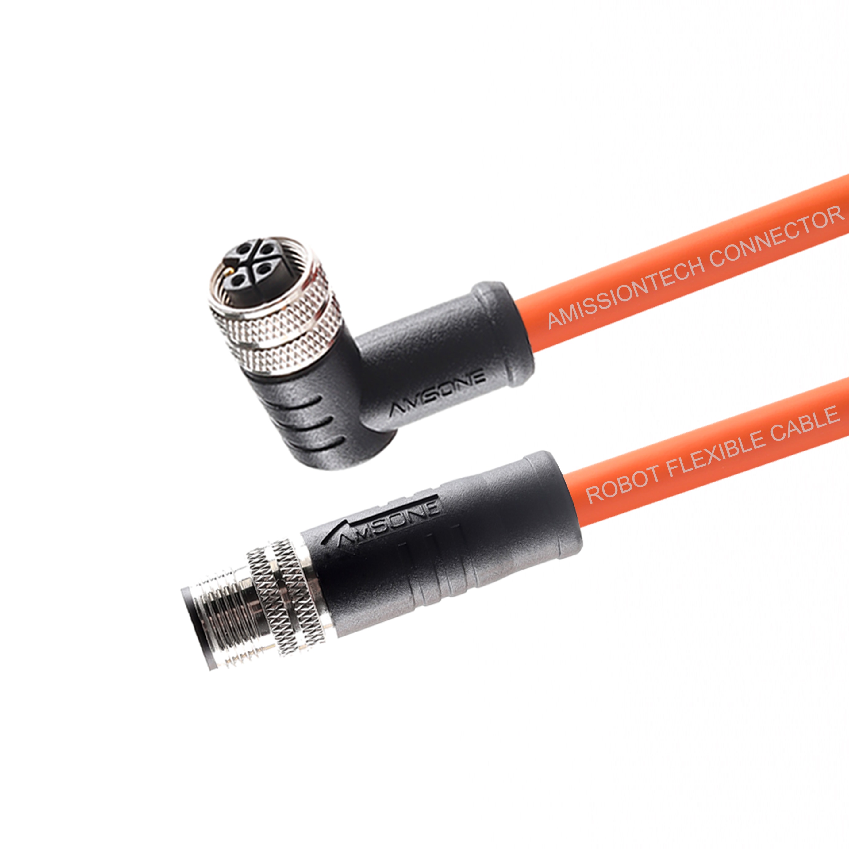
For high-flex applications like robotic cells or automated gantries, deploying rugged robot cables prevents conductor fatigue. Additionally, specifying coupling nuts with anti-vibration ratcheting mechanisms prevents hardware back-off, securing uninterrupted signal continuity across your harshest manufacturing axes.
Failure Three: Environmental Corrosion & Contact Oxidation

Corrosive environments rapidly degrade exposed metals, making them a top threat to outdoor and marine operations. When moisture, salt spray, or harsh industrial chemicals penetrate the housing, they trigger chemical reactions that permanently compromise electrical performance and signal clarity.

Mechanisms of Corrosive Damage

  • Galvanic Corrosion: Pairing mismatched metals—like a standard aluminum housing mating with a brass receptacle—in humid conditions creates a tiny electrical battery. This accelerated reaction destroys the weaker metal, pitting the hardware body.
  • Chemical Degradation: Airborne salinity along coastlines or caustic vapors in chemical processing lines aggressively attack base metals, coating critical contact pins in non-conductive green or black oxidation layers.
  • Plating Depletion: Exceeding a connector’s rated mating cycles wears away the microscopic gold or nickel finish. Once this happens, the highly reactive internal copper core is left completely exposed to atmospheric rust.

Material-Level Defenses

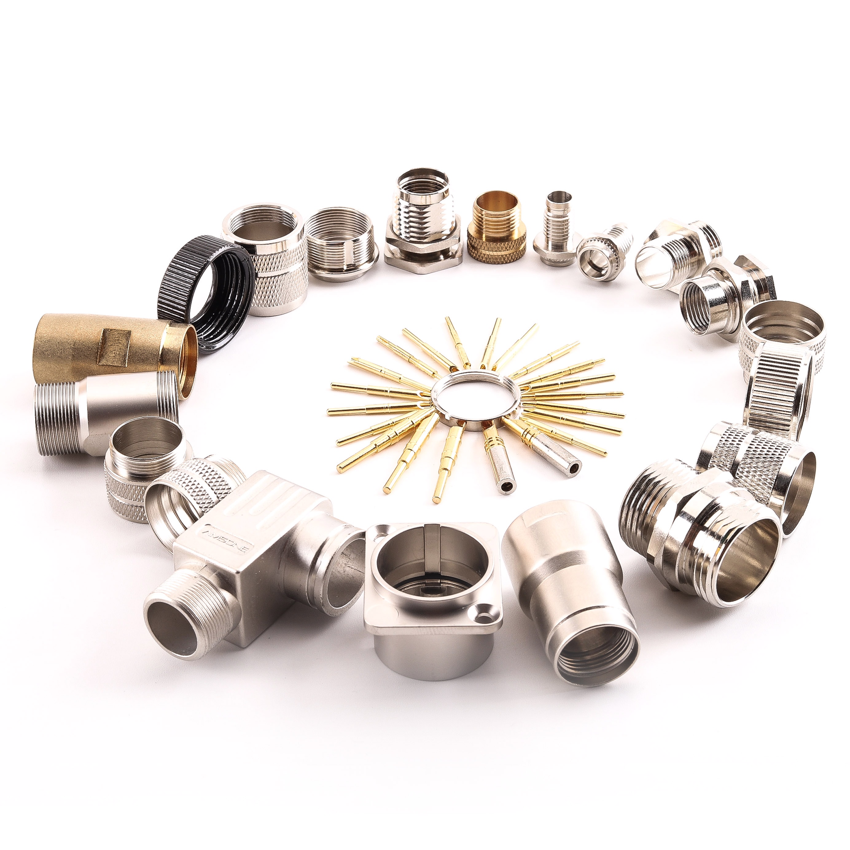
Protecting your signal pathways requires matching your connector metallurgy to the specific site environment. For heavy chemical or offshore applications, moving away from vulnerable aluminum or low-grade plastics toward marine-grade 316 stainless steel connectors provides complete immunity to salt pitting and corrosive vapors.

Additionally, always verify that your supplier uses a heavy nickel underplate topped with robust gold-plated contact pins. This metallurgical barrier maintains low contact resistance over years of harsh atmospheric exposure, preventing sudden voltage drops on critical data networks.

Failure Four: Installation Oversight & Field Assembly Errors

Even the most robust hardware will fail if it is poorly assembled on the factory floor. Field errors during initial installation represent a significant percentage of early-stage network failures, leading to immediate water leaks, crossed signals, or erratic device behavior upon system startup.

Common Assembly Mistakes

  • Thread Over-Torqueing: Forcing threaded joints beyond their mechanical limits deforms internal plastic carriers, strips metal threads, and crushes elastomer O-rings, turning a protective seal into a leak path.
  • Improper Cable Stripping: Stripping insulation jackets too long or too short allows stray copper strands to cause short circuits, or pinches conductor insulation under the sealing grommet, ruining the gas-tight fit.
  • Unmated Port Exposure: Leaving live, open receptacles unprotected on the plant floor during installation or routine maintenance cycles allows moisture, dust, and cutting fluids to settle directly inside the contact chambers.

Procedural Solutions

Eliminating installation variables requires standardized field practices. Equip your maintenance crews with calibrated torque wrenches and enforce strict adhesion to manufacturer torque specifications to prevent both under-tightening and over-torqueing.

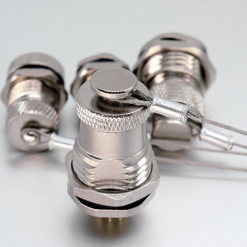
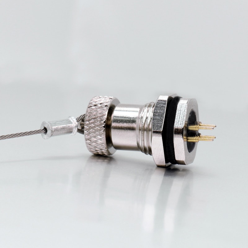
To completely bypass manual wire-stripping risks, utilize pre-terminated cable assemblies where possible. Finally, secure every unused open port with heavy-duty dust protective caps immediately; this simple step keeps inner pin layouts isolated from airborne contaminants until the final connection is made.
Laboratory Validation: Testing Protocols for Industrial Reliability

Before deploying components to your plant floor, rigorous laboratory testing is essential to simulate years of field abuse. True industrial-grade hardware must pass standardized environmental and mechanical stress tests to guarantee long-term field survivability.

Key Testing Standards

  • Thermal Shock Testing: Components undergo rapid cycling between extreme temperatures (e.g., -40°C to +85°C) to ensure the housing materials and internal seals won't crack or separate under sudden climate shifts.
  • IPX9K High-Pressure Washdown: This test subjects the mated connectors to high-pressure (up to 100 bar) streams of 80°C hot water from multiple angles, validating their resistance to harsh sanitation protocols.
  • Mechanical Endurance Cycles: Connectors are repeatedly mated and unmated hundreds of times to measure plating wear on the contact pins, ensuring contact resistance remains low over the product's lifespan.

Customization and Application-Specific Engineering

Standard off-the-shelf components cannot solve every unique industrial challenge. When dealing with specialized machinery, tight spatial constraints, or proprietary signal layouts, tailored interconnect engineering becomes a operational necessity.

Tailored Integration Solutions

  • Custom Pin Configurations: Mixing power and high-speed data lines within a single custom connector shell reduces your overall hardware footprint and simplifies field wiring.
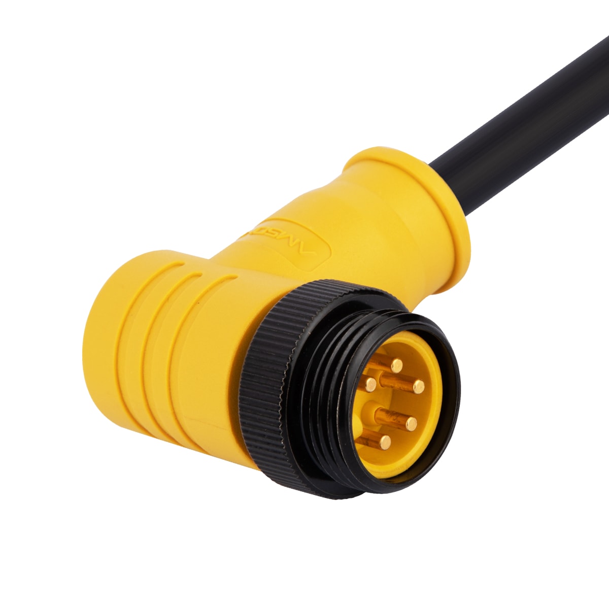
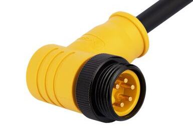
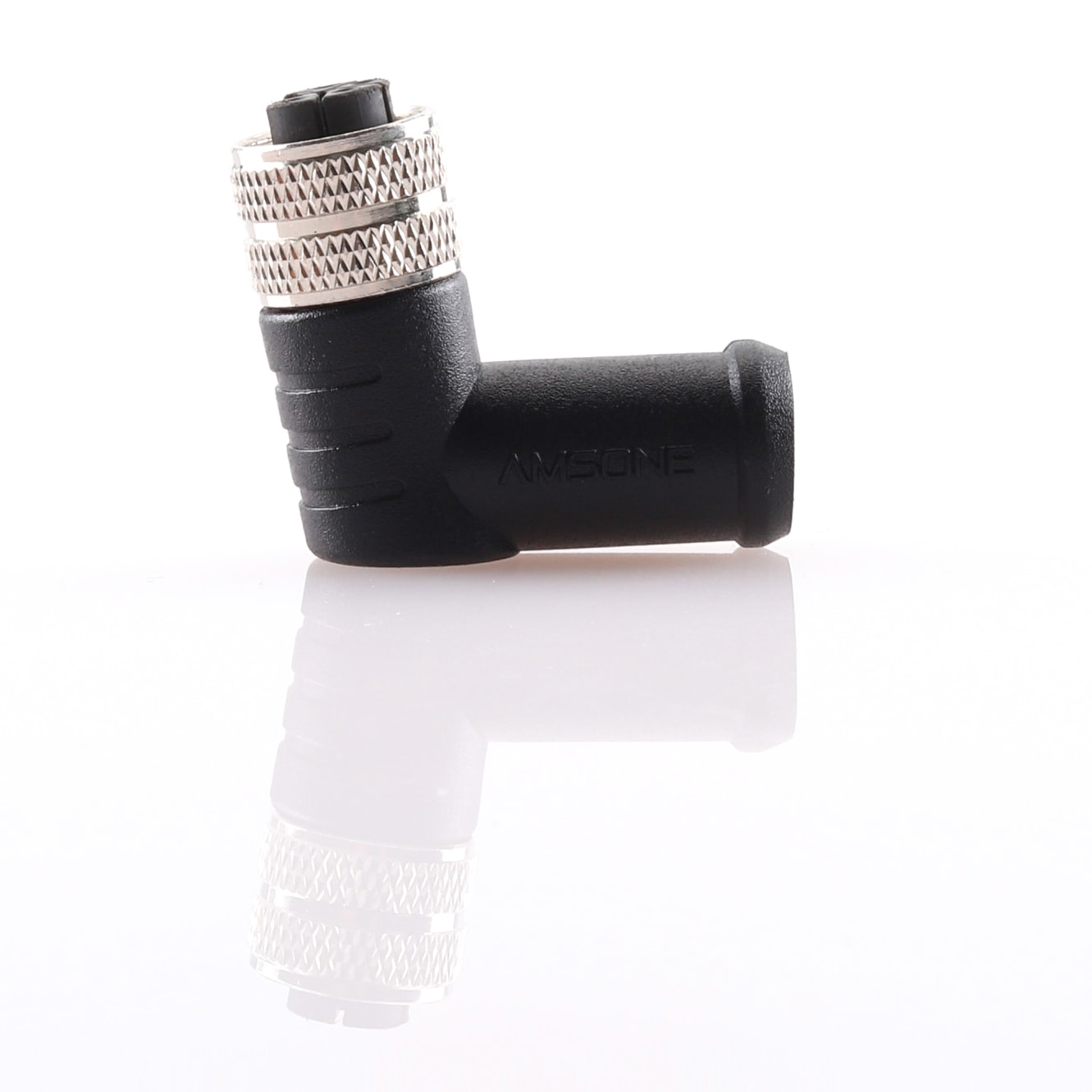
  • Bespoke Cable Overmolding: Designing unique right-angle or space-saving overmold profiles allows cables to route smoothly around tight structural framing without exceeding their safe bend radius.
  • Specialized Jacket Materials: Depending on your environment, you can specify specialized outer jackets—such as halogen-free (LSZH) or mud-resistant compounds—to meet strict regional safety regulations.

Final thoughts

Eliminating connectivity failures requires matching your hardware to your exact environmental demands. Protect your uptime today— contact us to discuss your specific application needs with our engineering team.

Amissiontech Co., Ltd
Your Demand,Our Desire!
×

Inquire

*Name
*Email
Company Name
Tel
*Message
*Verify Code
captcha
×

Contact Us

captcha

*We respect your privacy. When you submit your contact information, we agree to only contact you in accordance with our Privacy Policy.