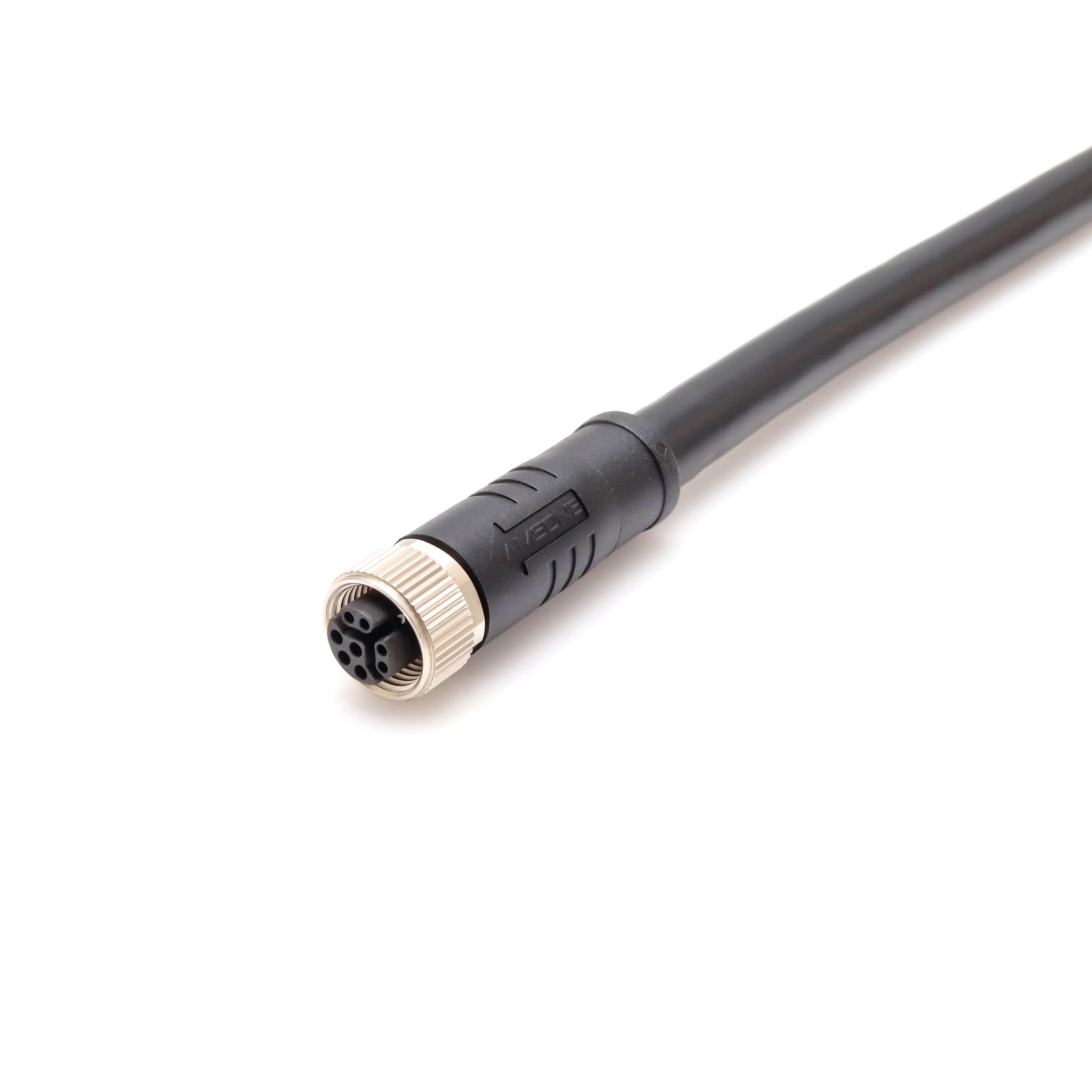
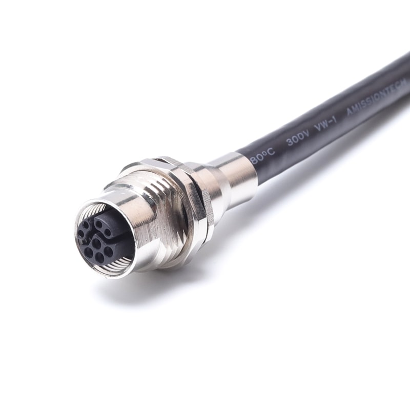
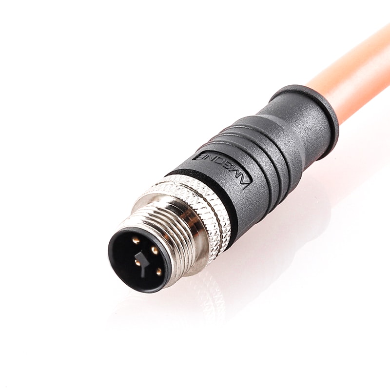
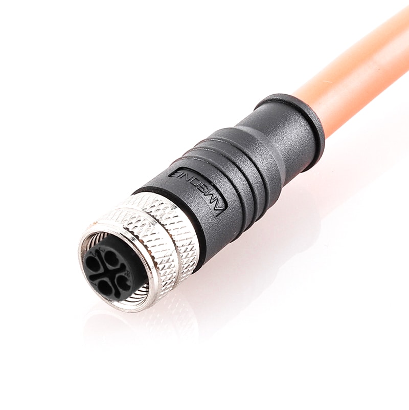
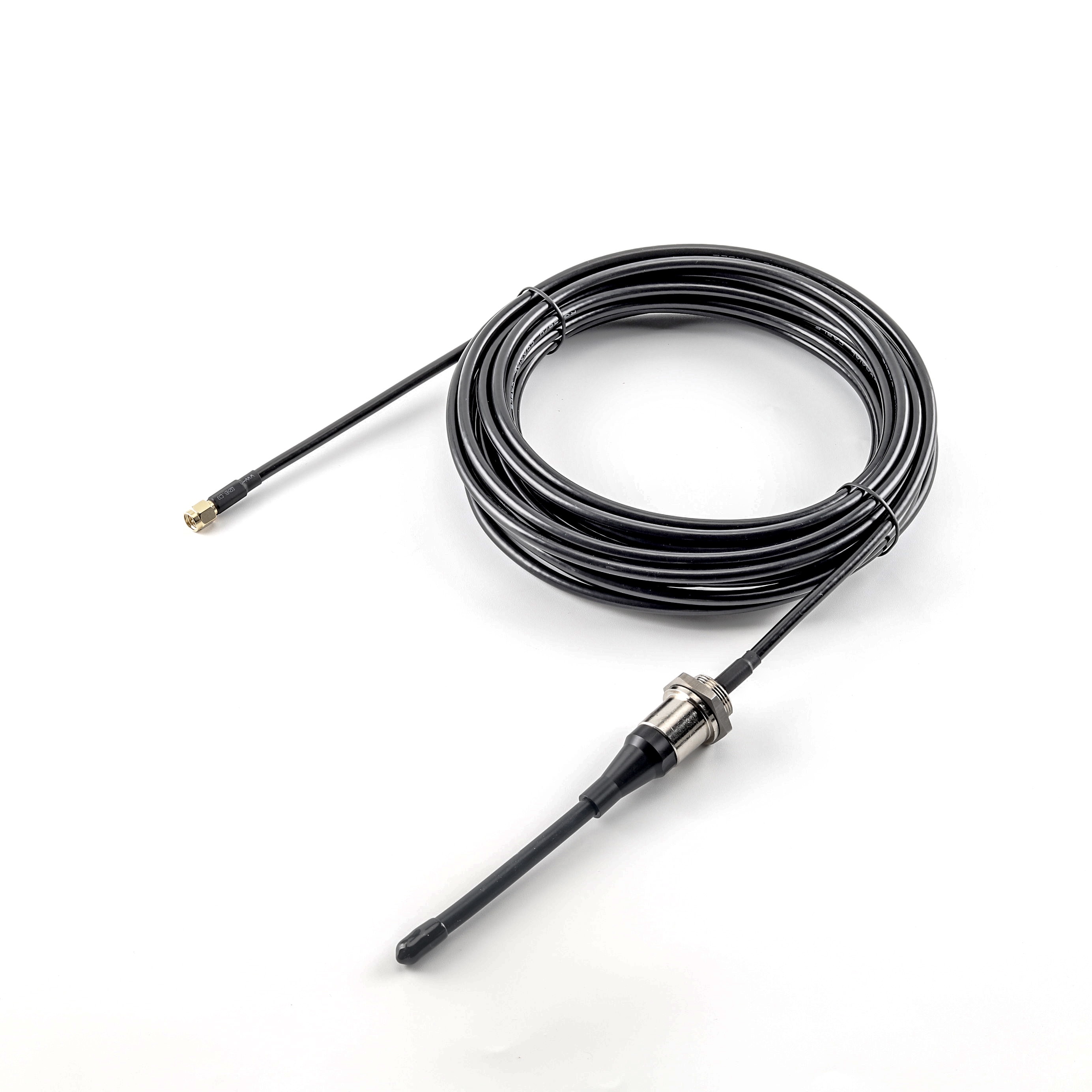
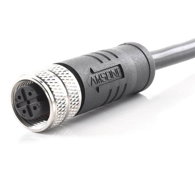
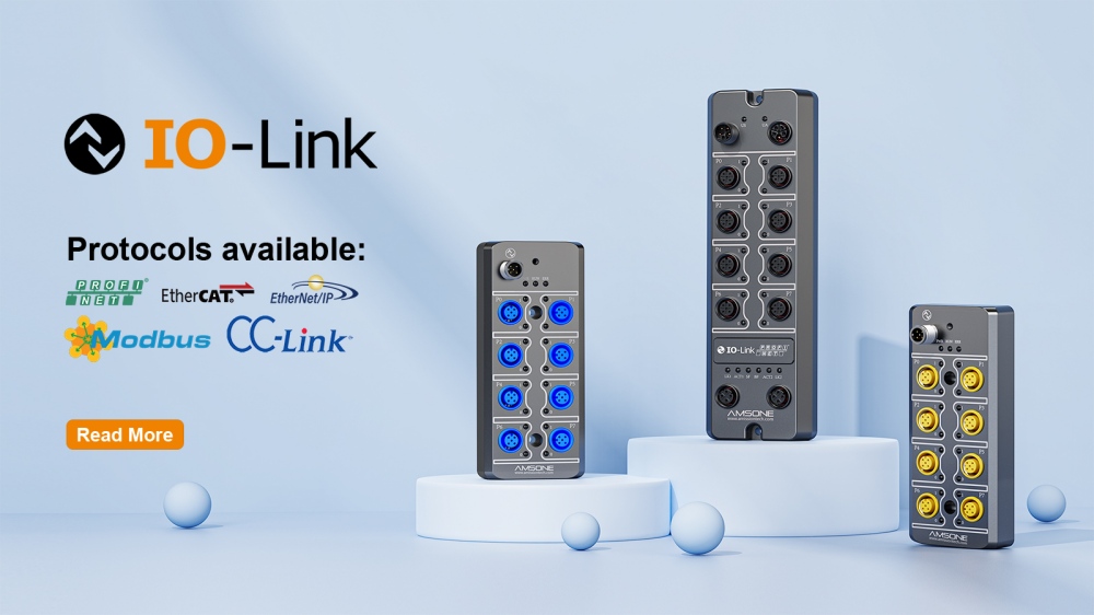
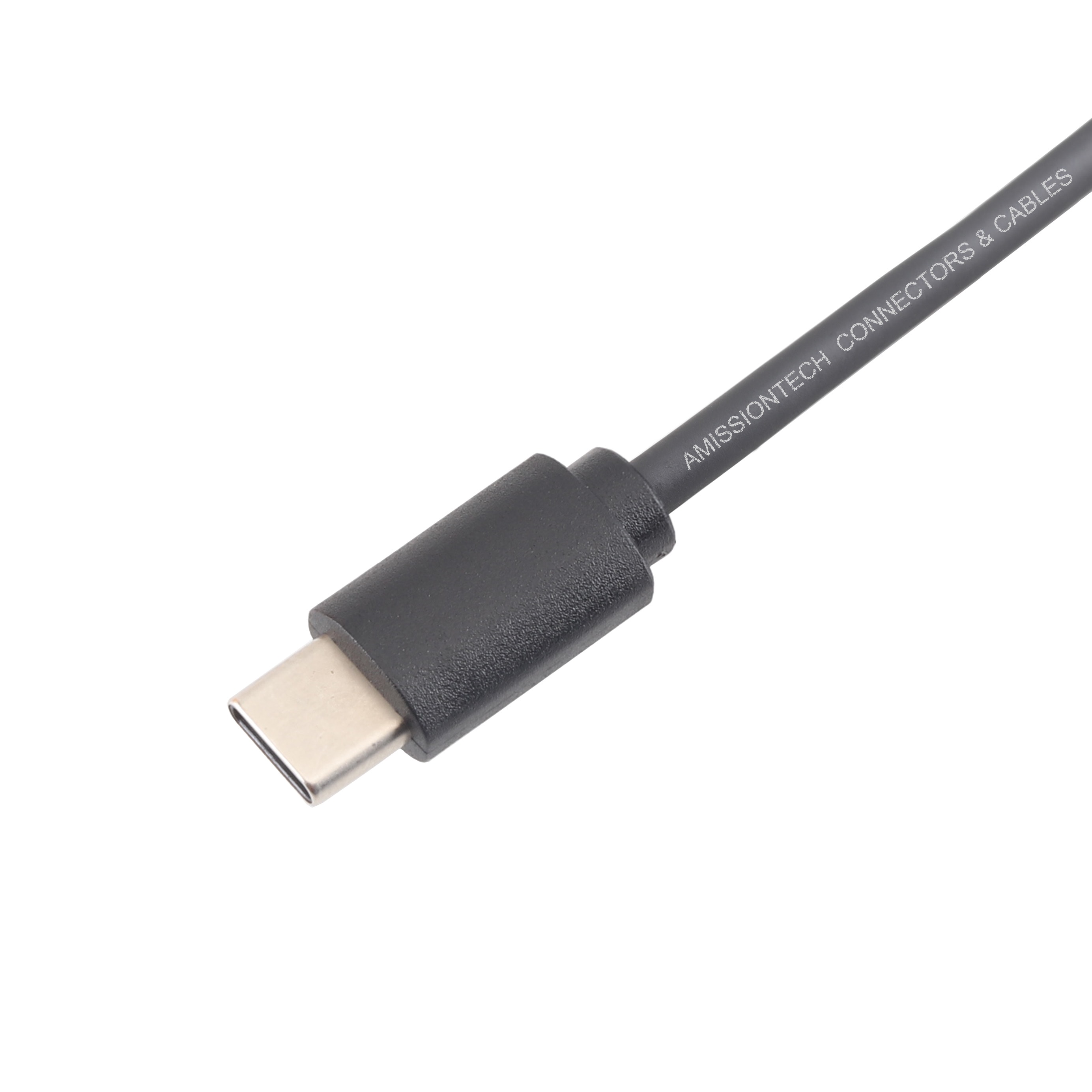
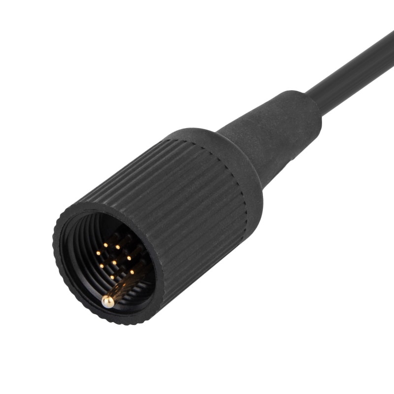
IO-Link is a point-to-point serial communication protocol defined by IEC 61131-9. It connects IO-Link sensors and actuators to industrial controllers via standard 3-wire unshielded M12 cables, replacing analog wiring with digital bidirectional data exchange for process, parameter, and diagnostic information.
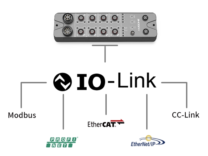
At system level, IO-Link uses a master-device architecture. The master bridges field devices and industrial networks such as PROFINET, EtherNet/IP, EtherCAT, and Modbus TCP. It supports COM1, COM2, and COM3 speeds, while IODD files ensure plug-and-play interoperability across vendors.
IO-Link simplifies industrial automation by reducing wiring complexity, enabling centralized parameter management, and supporting real-time diagnostics for predictive maintenance and flexible production systems.
Core IO-Link System Architecture
Master and Device Communication Model
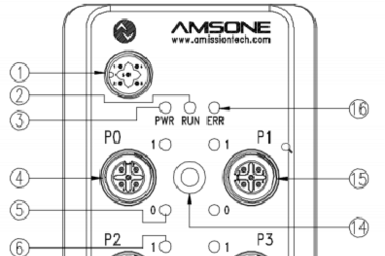
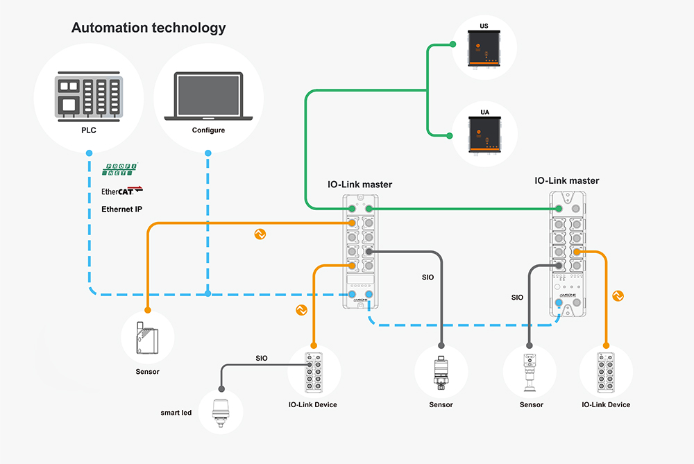
An IO-Link system consists of an IO-Link master and one or more IO-Link devices connected in a point-to-point topology. Each master port communicates with a single device, eliminating address configuration and simplifying commissioning.
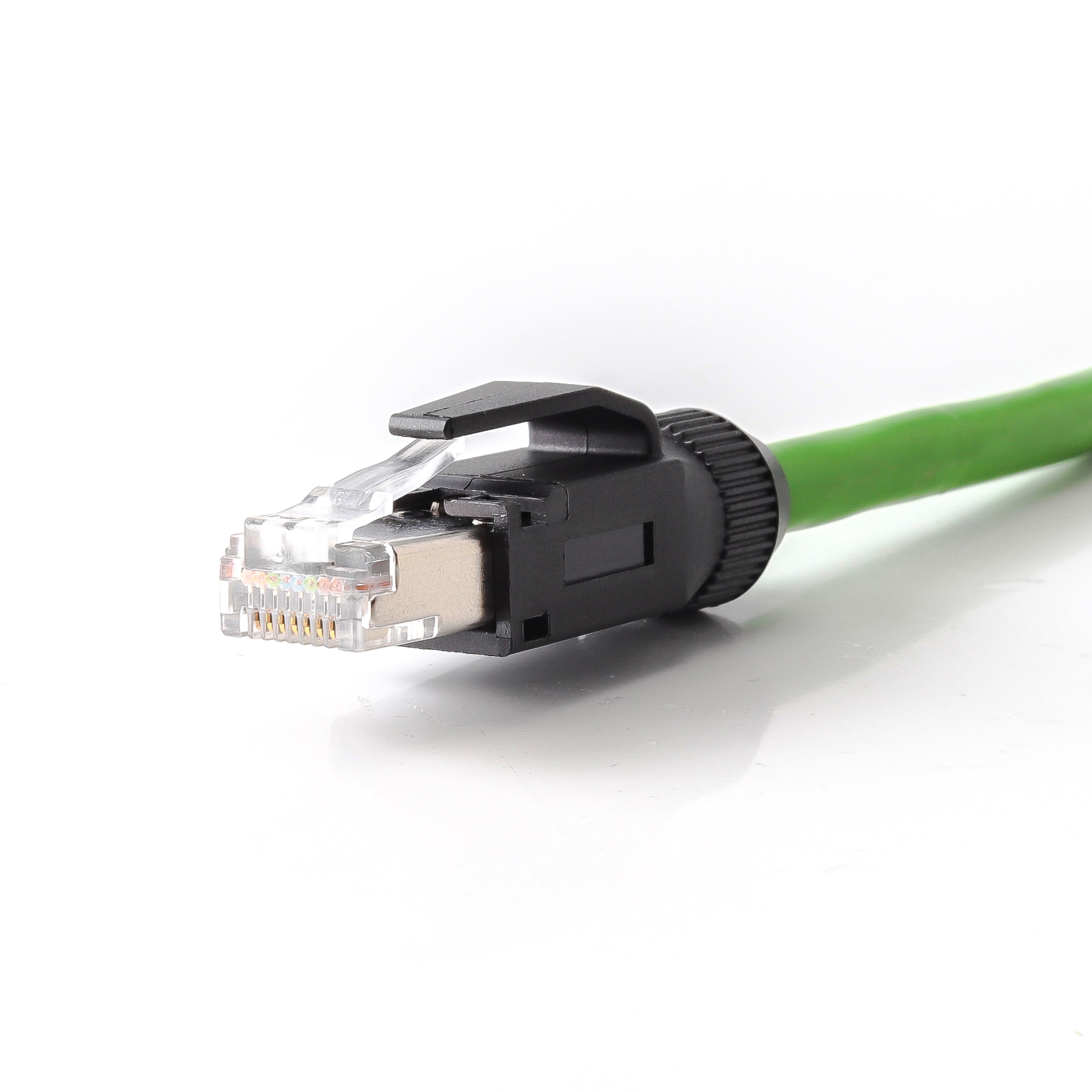
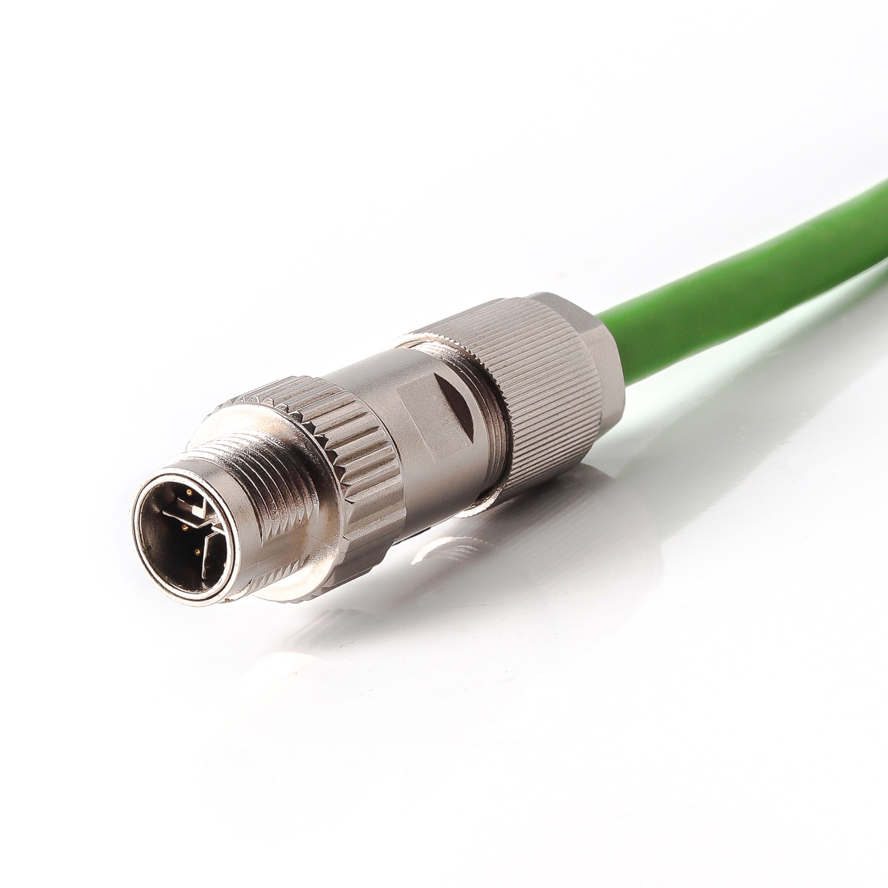
The master acts as a gateway between field-level devices and the higher-level fieldbus or industrial Ethernet network. It translates IO-Link telegrams into PROFINET, EtherNet/IP, EtherCAT, or Modbus TCP frames.
Communication Modes and Data Rates
IO-Link defines three standardized communication speeds for different device complexity levels. SIO mode maintains backward compatibility with standard digital I/O, allowing legacy sensors to operate on the same port without protocol negotiation.
COM1 operates at 4.8 kbaud and serves simple switching devices such as inductive proximity sensors. COM2 at 38.4 kbaud handles medium-complexity devices including pressure transmitters and flow meters. COM3 at 230.4 kbaud supports advanced smart sensors such as laser distance sensors and RFID read/write heads.
IO-Link Data Types and Parameter Management
Process data carries real-time sensor measurements and actuator setpoints in cyclic frames. The data width ranges from 1 byte for simple on/off signals up to 32 bytes for complex multi-variable sensors.
Service data handles acyclic parameter read and write operations during device configuration. Event data transmits diagnostic messages, warnings, and error codes independently of the cyclic data stream. This enables asynchronous notification of device faults without disrupting normal process communication.
IODD files define every parameter, data structure, and communication property of an IO-Link device in a standardized XML format. These device description files enable plug-and-play interoperability across manufacturers.
Any IO-Link master from any supplier can interpret any device manufacturer's IODD file through a common engineering tool. This eliminates vendor lock-in during system integration and allows OEMs to source devices from multiple qualified suppliers.
Technical Benefits in Industrial Automation Environments
Reduced Wiring Complexity and Installation Cost
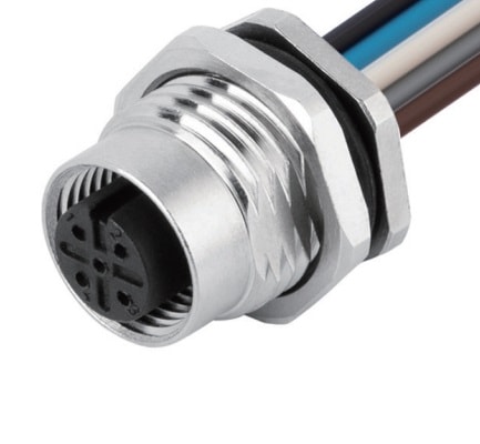
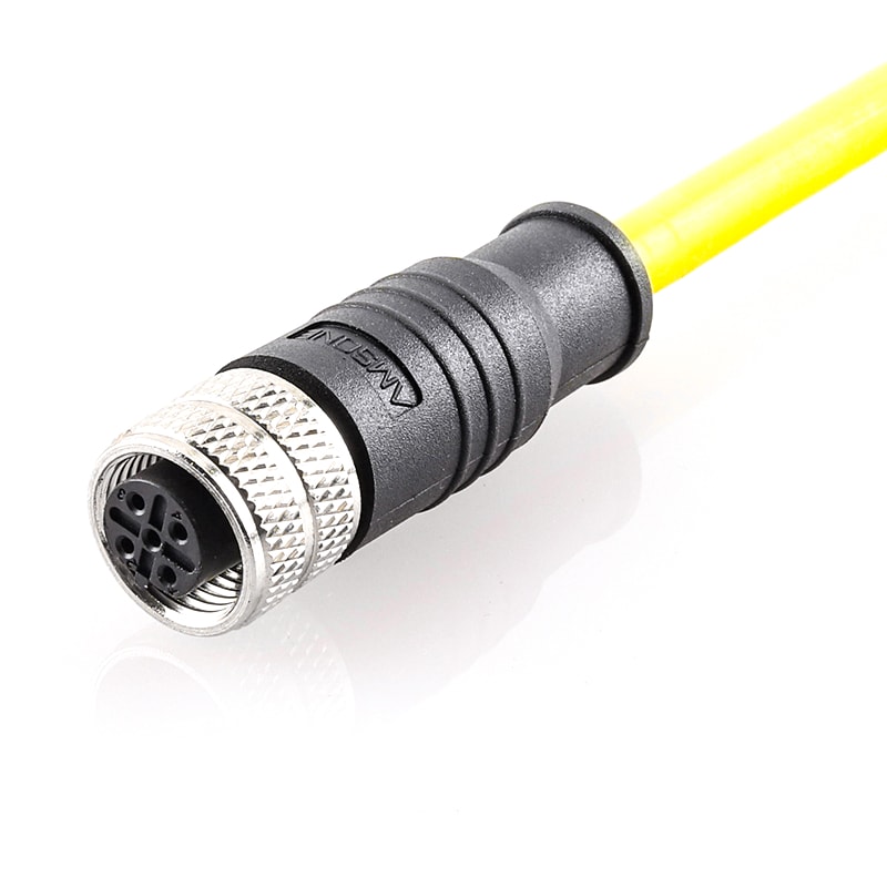
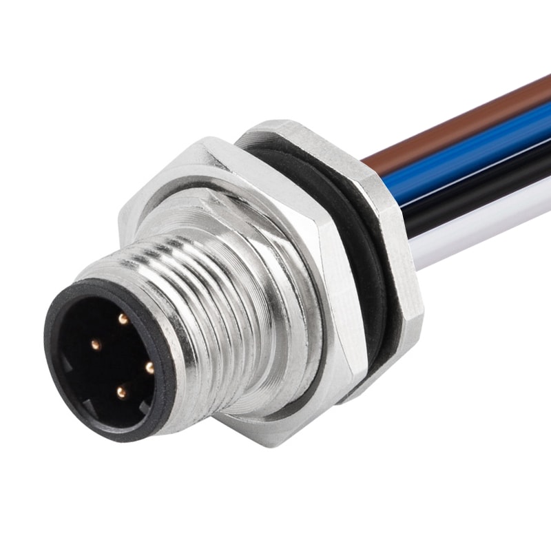
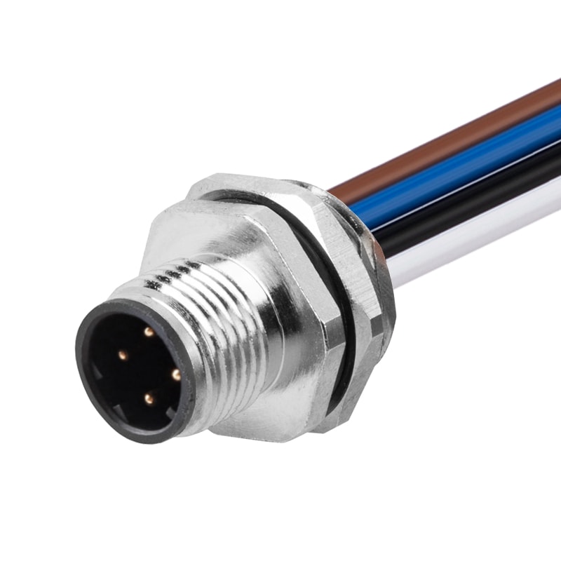
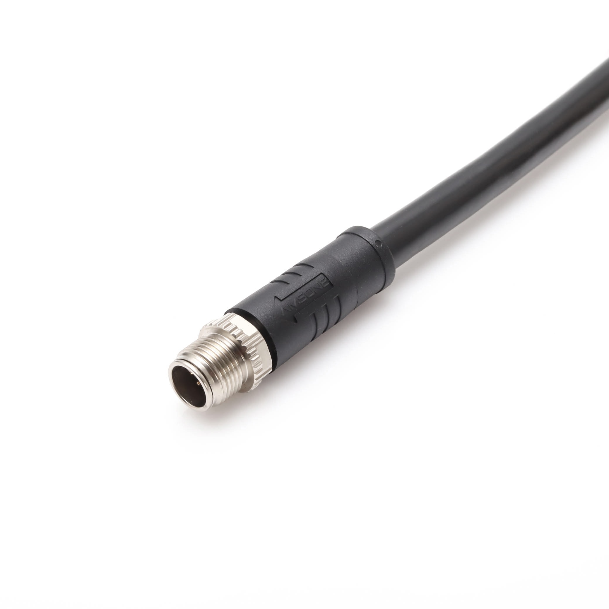
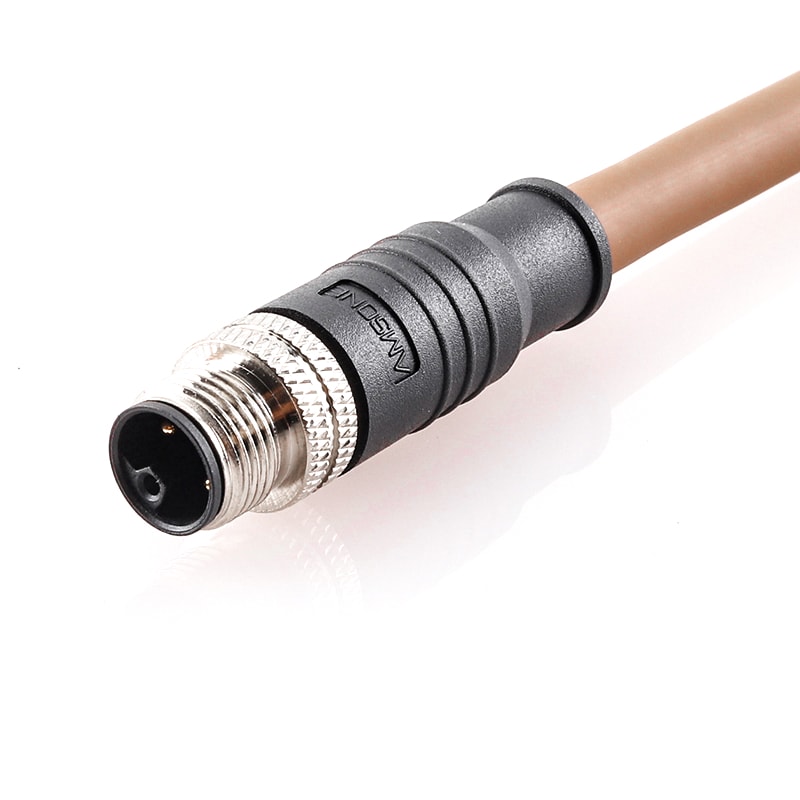
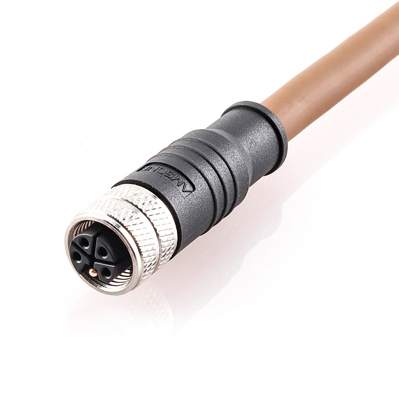
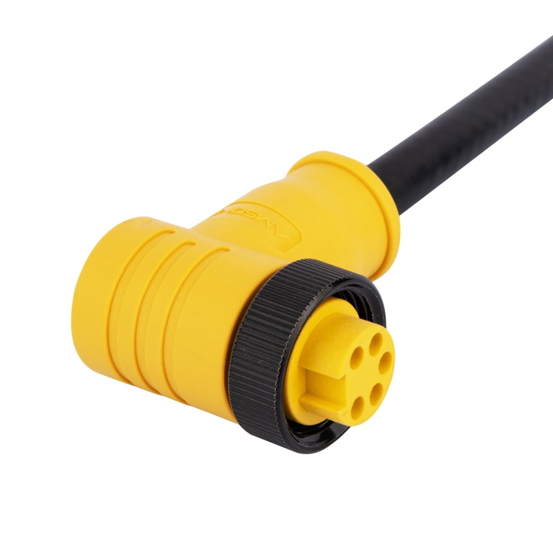
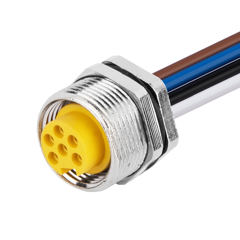
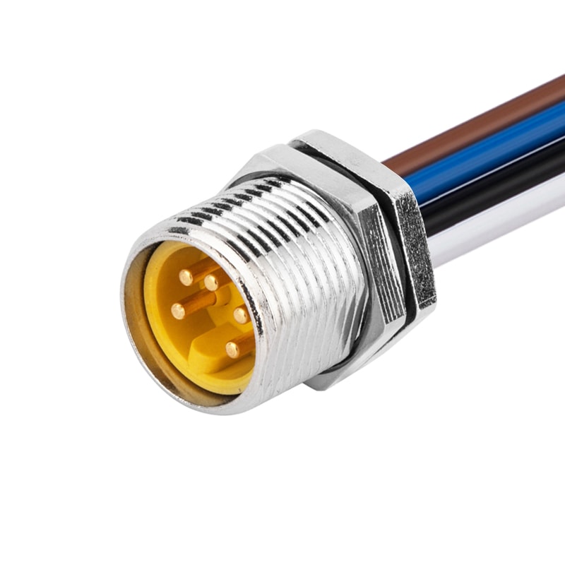
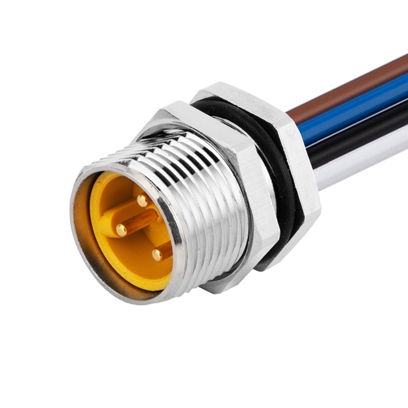
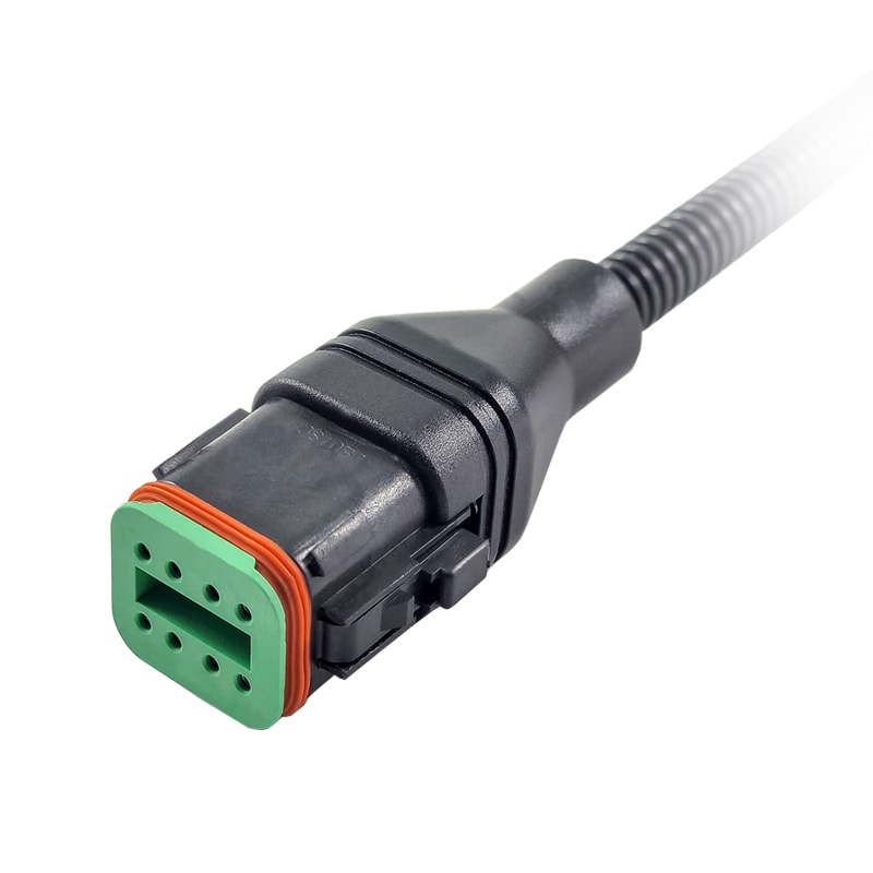
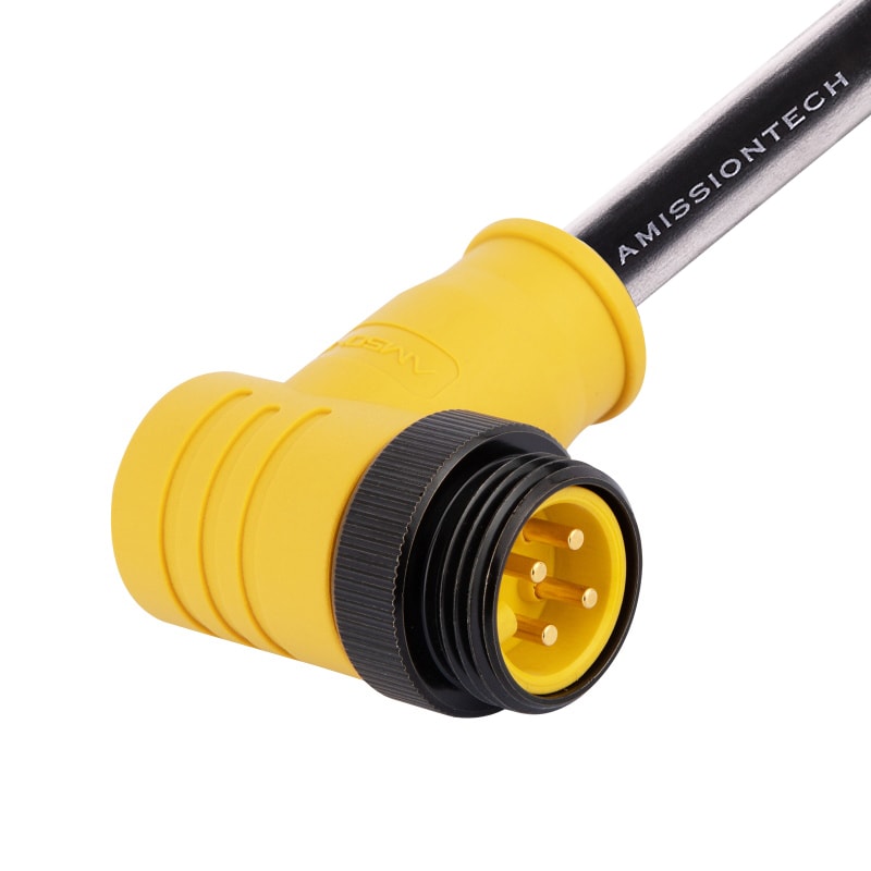
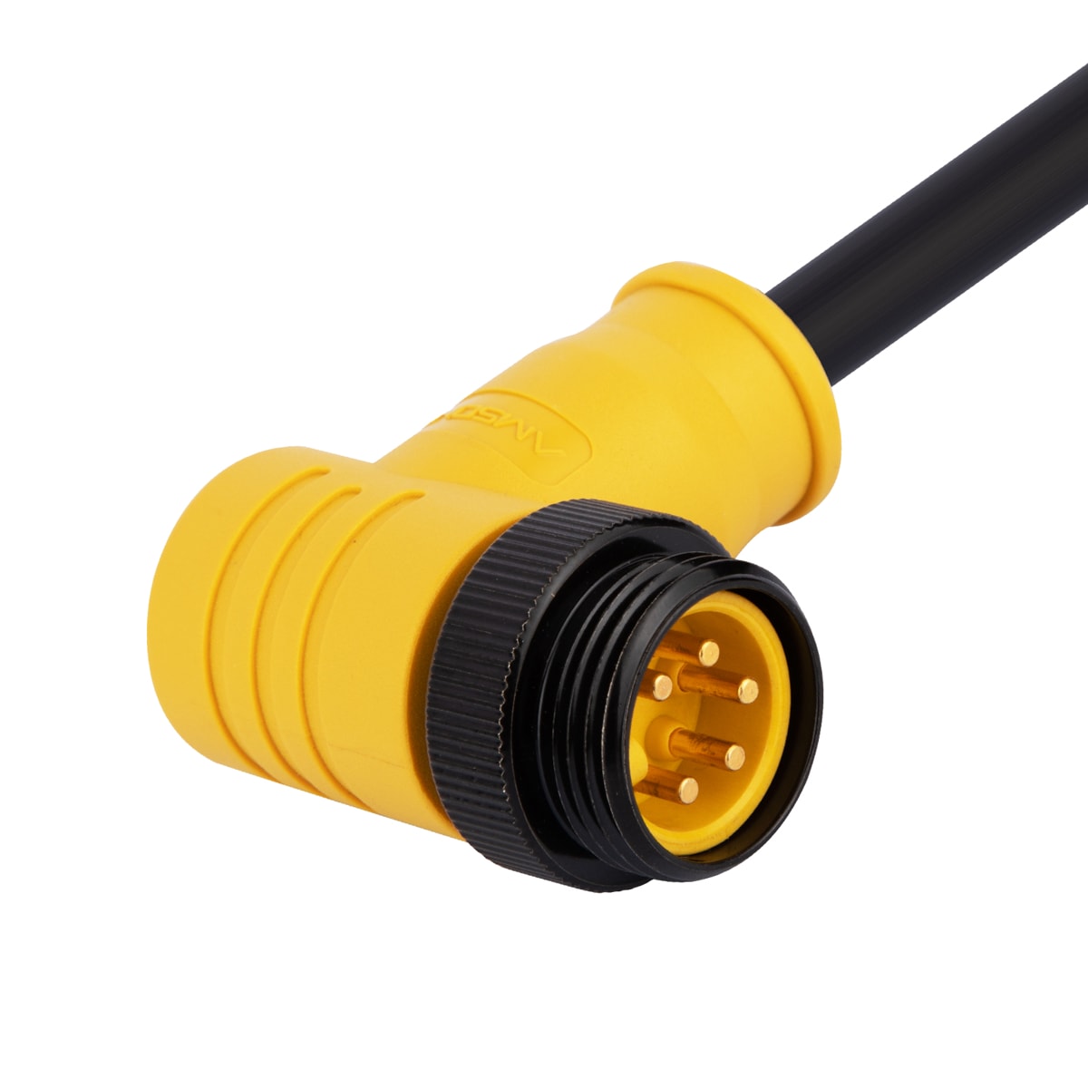
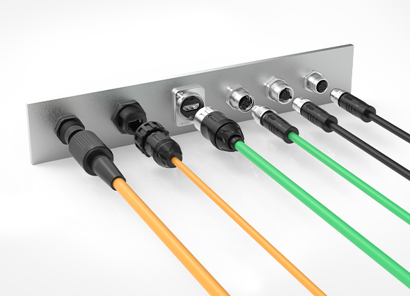
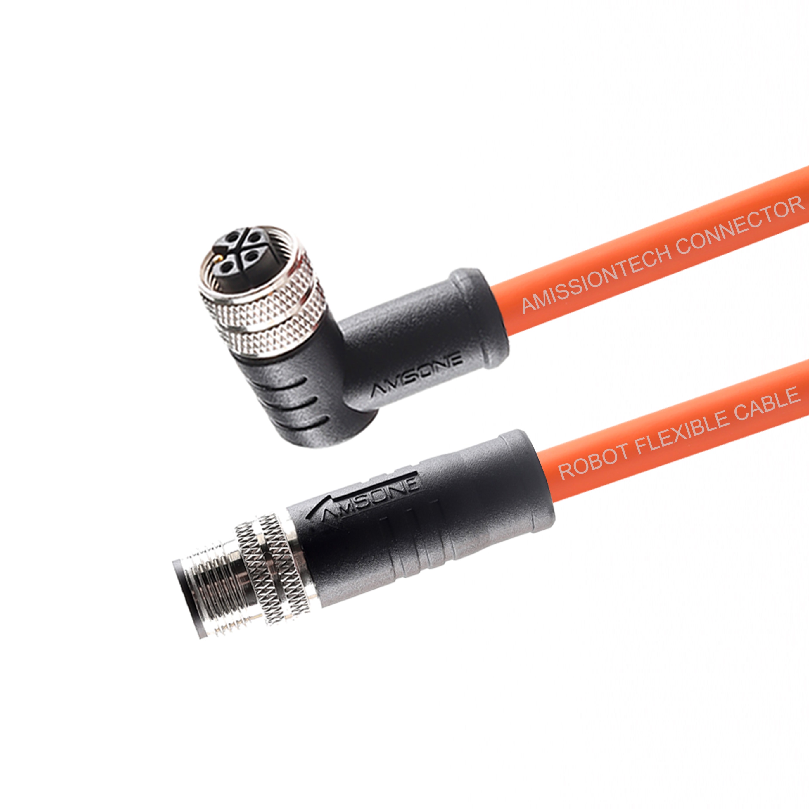
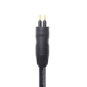
Standard M12 connectors carry power and data on three unshielded conductors. This replaces the multi-conductor cables required for analog sensors. Field installers replace devices without recalibrating analog input modules on the PLC. Pre-configured parameter sets autoload from the master upon device replacement, reducing labor and eliminating wiring errors.
Centralized Parameter Management and Backup
IO-Link masters store device parameter sets as backup copies in non-volatile memory. When a sensor fails and is physically replaced, the master automatically downloads the stored parameters to the new unit.
This eliminates manual reconfiguration steps and reduces mean time to repair on the production floor. It also prevents parameter entry errors during maintenance windows.
Real-Time Condition Monitoring and Diagnostics
Devices continuously transmit health status indicators, cumulative operating hours, internal temperature readings, and error counters alongside process data. Maintenance teams access this diagnostic data stream through the existing PLC or SCADA system without adding extra sensors or wiring.
Predictive maintenance algorithms running on the controller can trigger service interventions before unplanned downtime occurs.
Flexible Production Changeovers
Multi-recipe sensor configurations load parameter sets on demand from the PLC. A single IO-Link sensor switches between measurement ranges, filter settings, and output functions for different product variants without physical adjustment.
Automotive assembly lines use this capability to handle multiple vehicle models on a single production line. Automatic sensor reconfiguration occurs between batches without operator intervention.
Device Identification and Inventory Management
Each IO-Link device carries a unique vendor ID, device ID, and serial number accessible through the master. Asset management systems read this identity data to maintain an accurate digital twin of the installed field device population. This data supports automated spare parts ordering, warranty tracking, and lifecycle management programs.
Device Integration and Wiring Topology
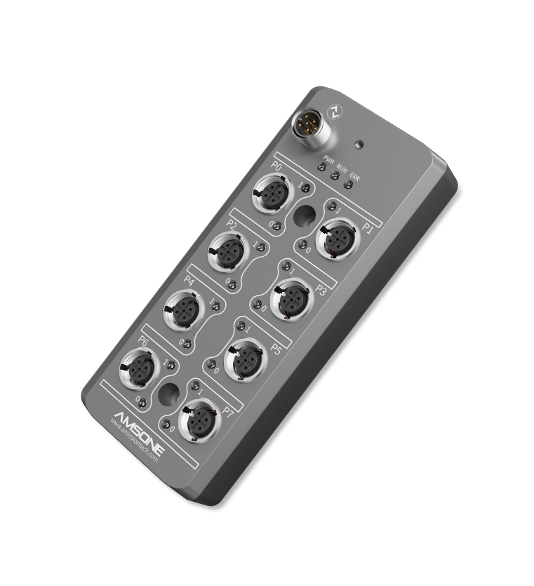
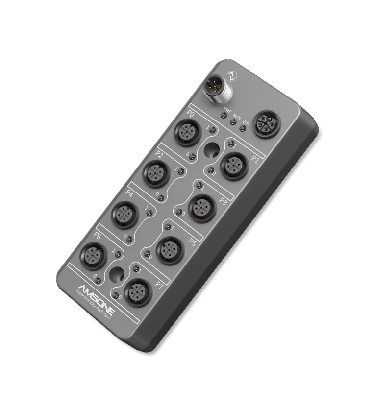
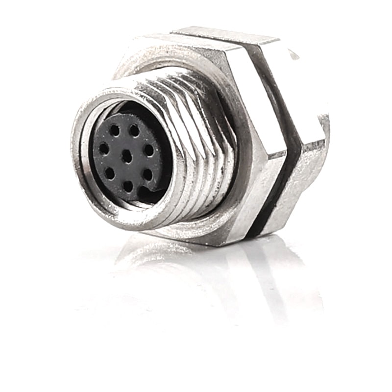
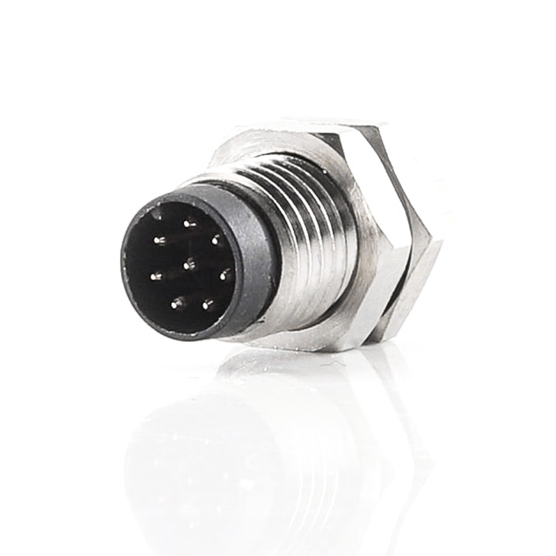
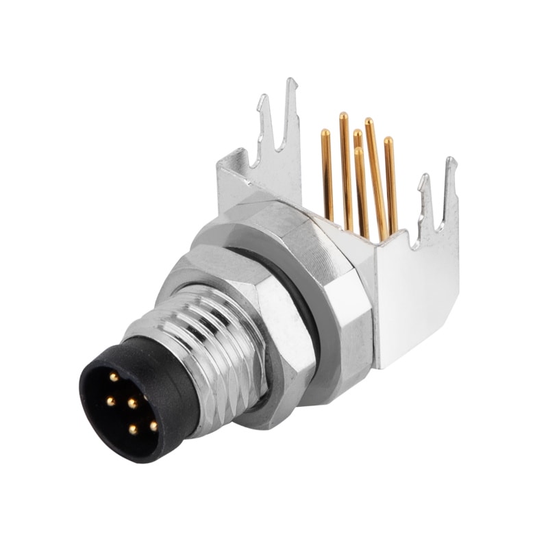
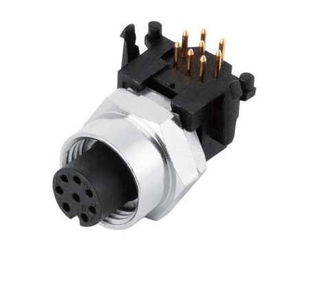
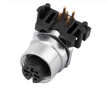
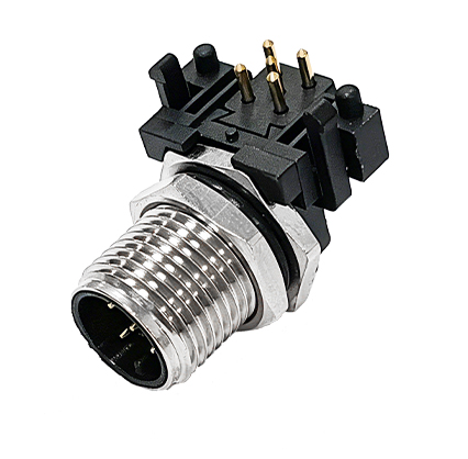
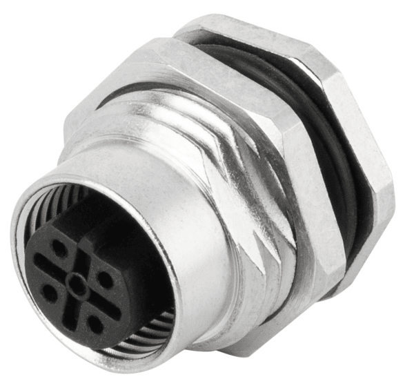
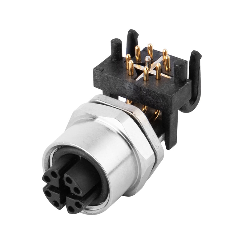
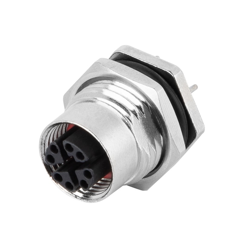
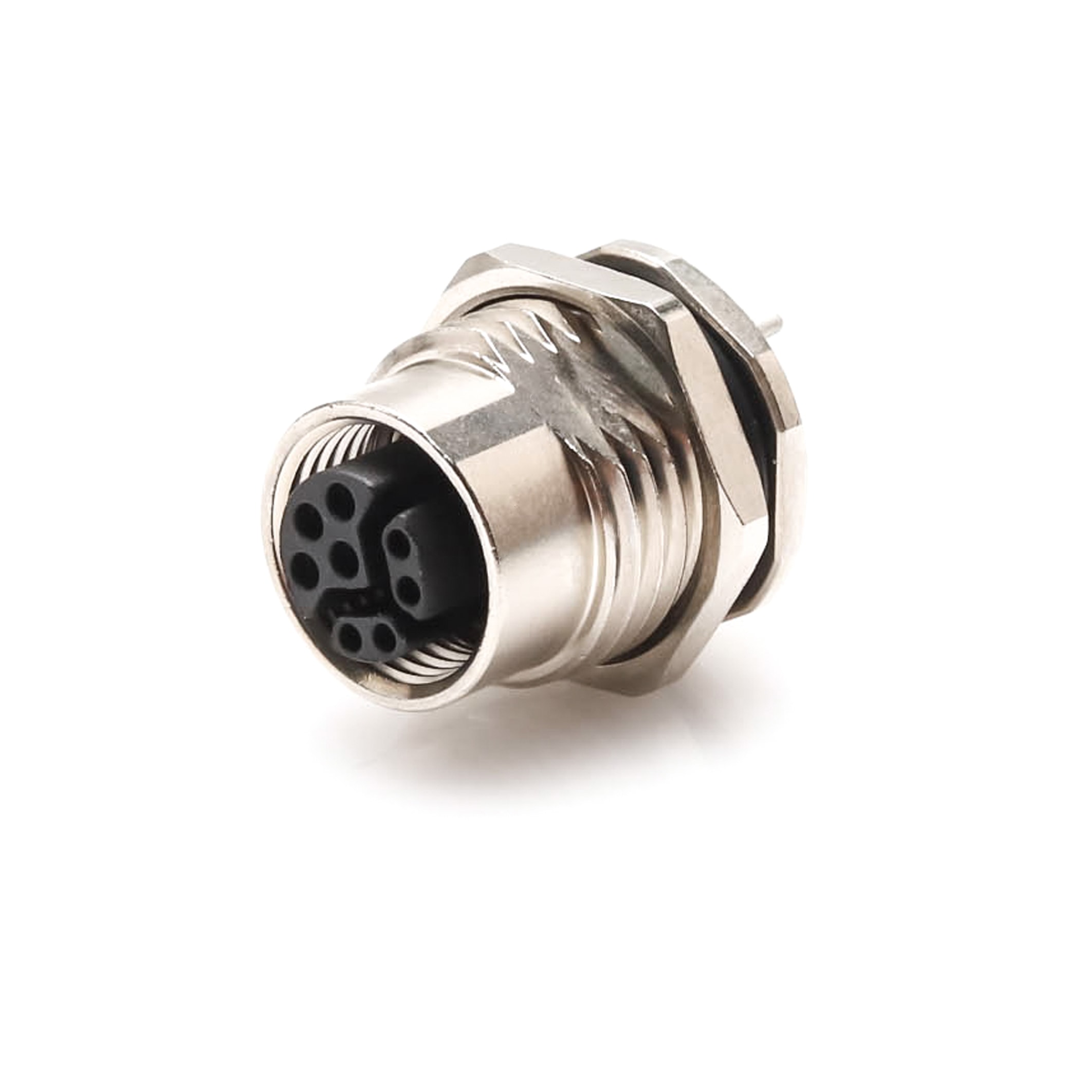
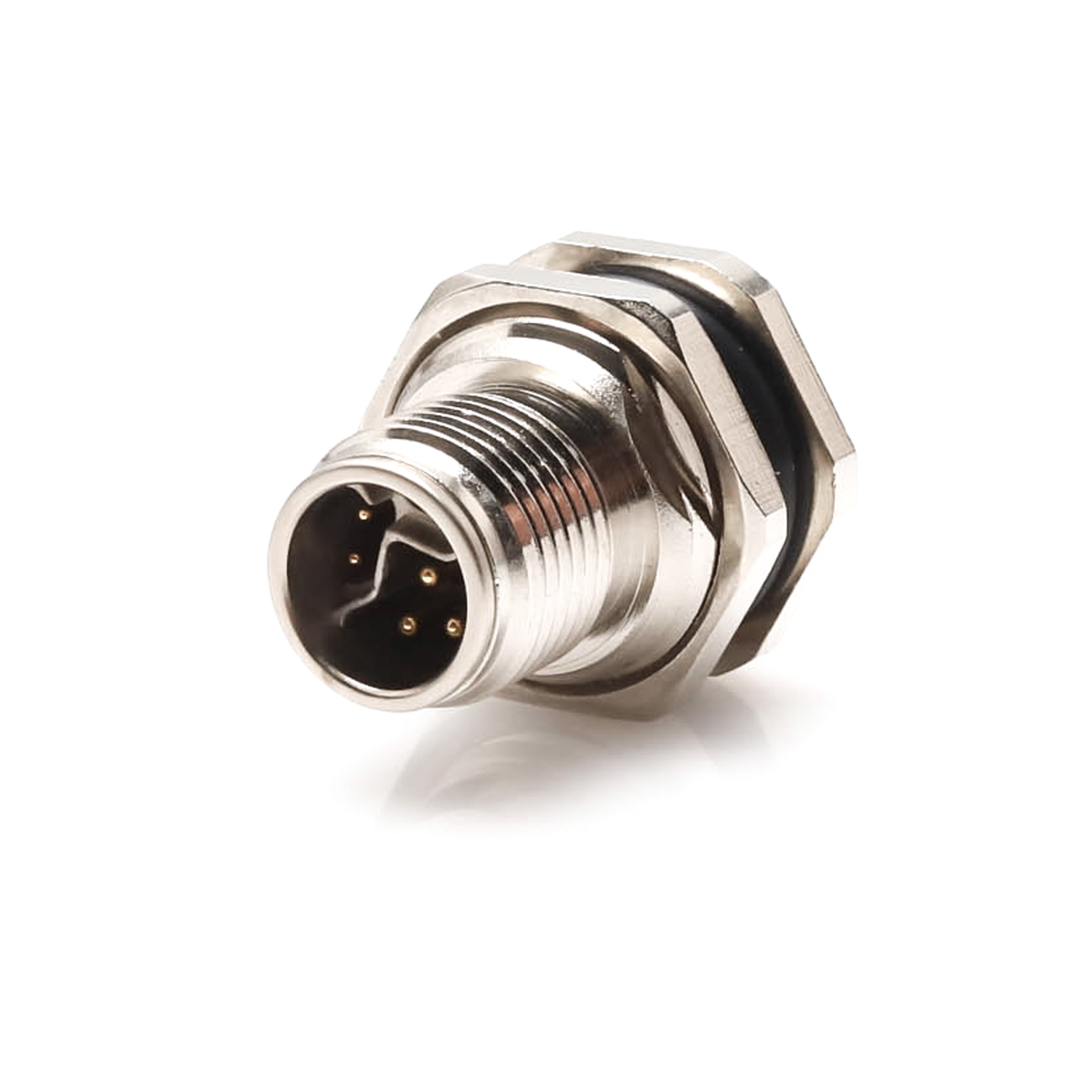
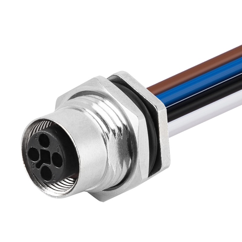
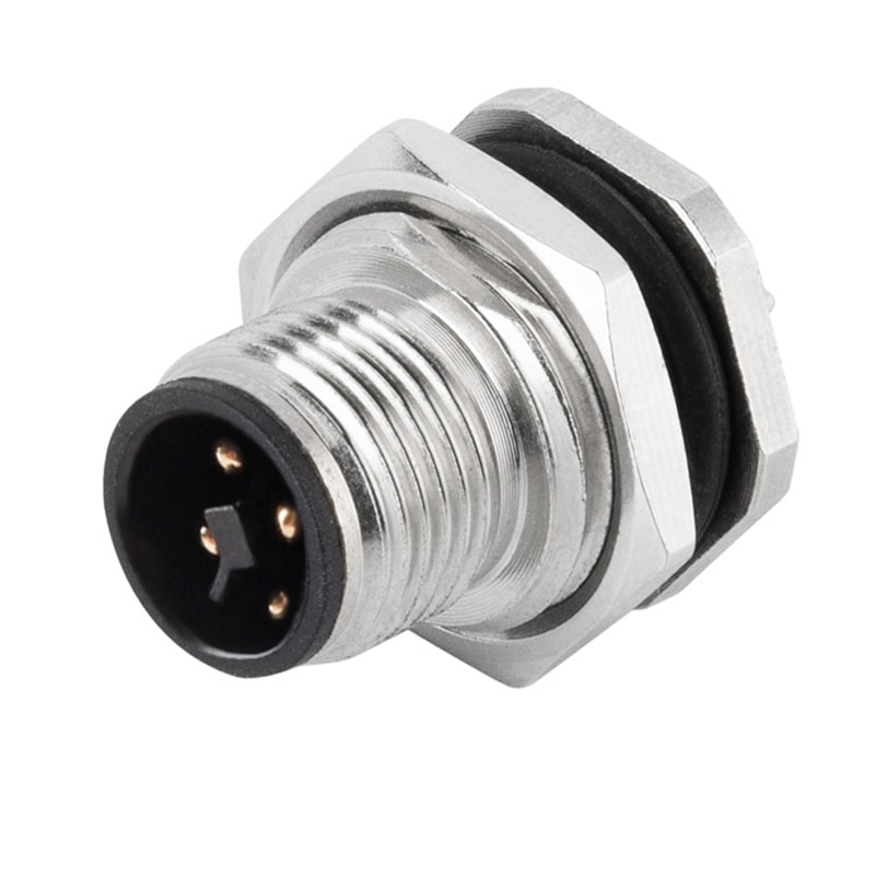
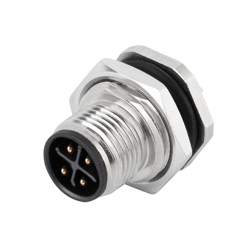
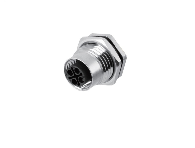
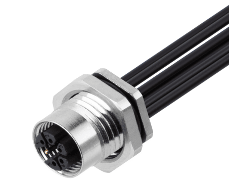
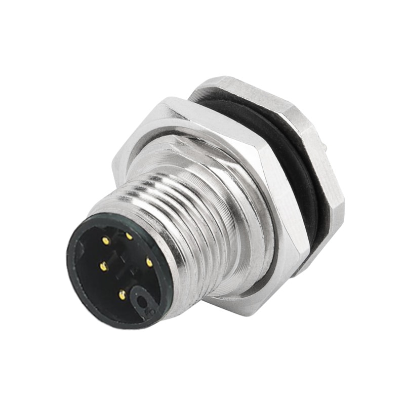
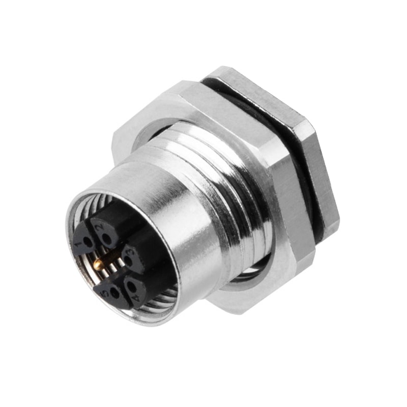
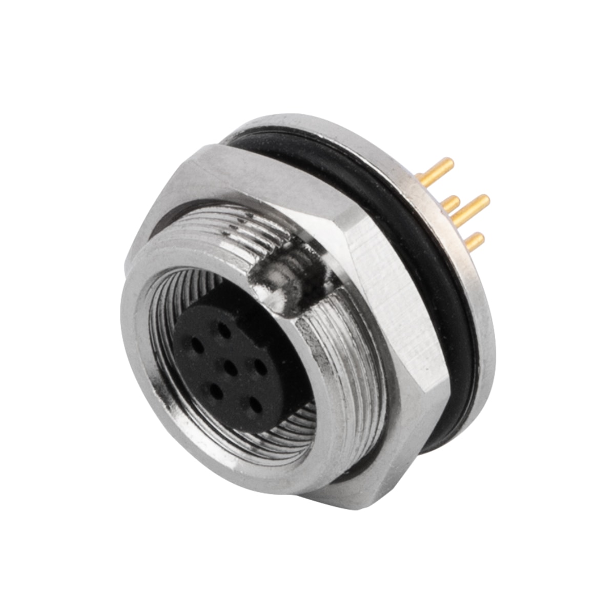
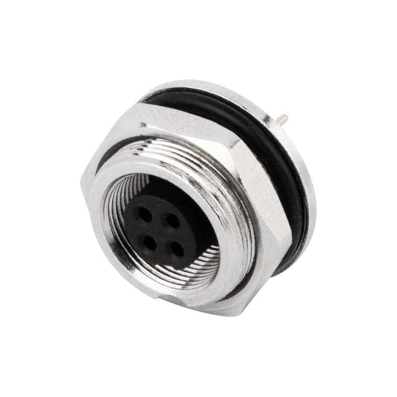
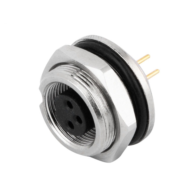
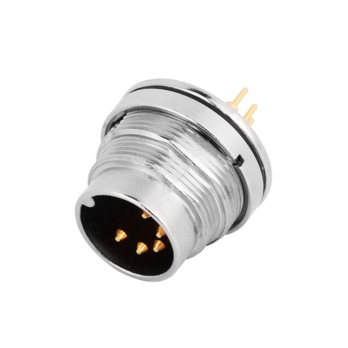
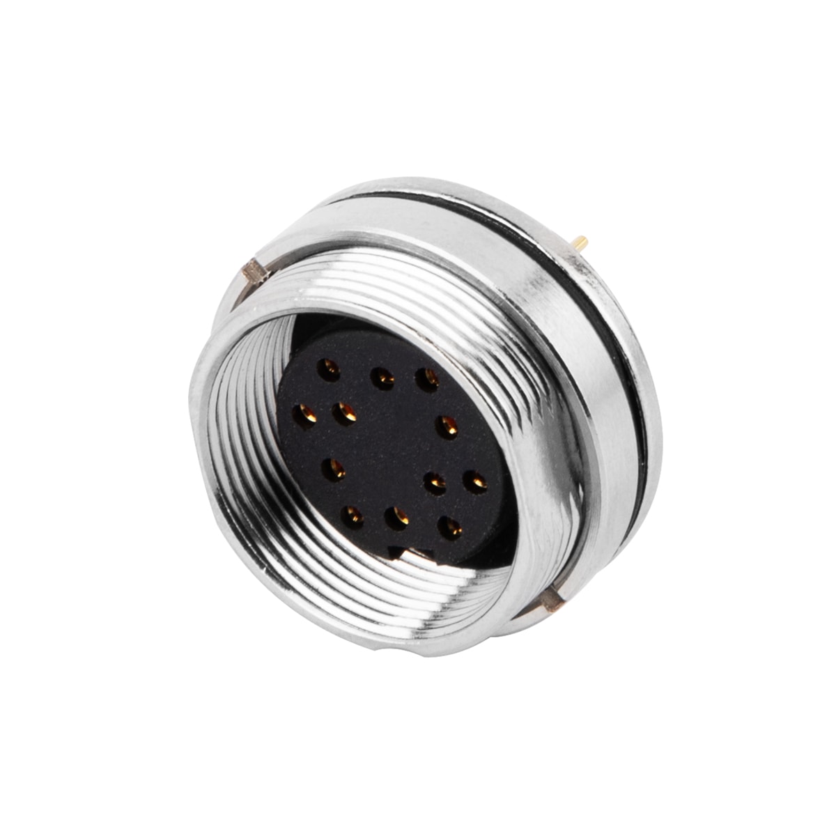
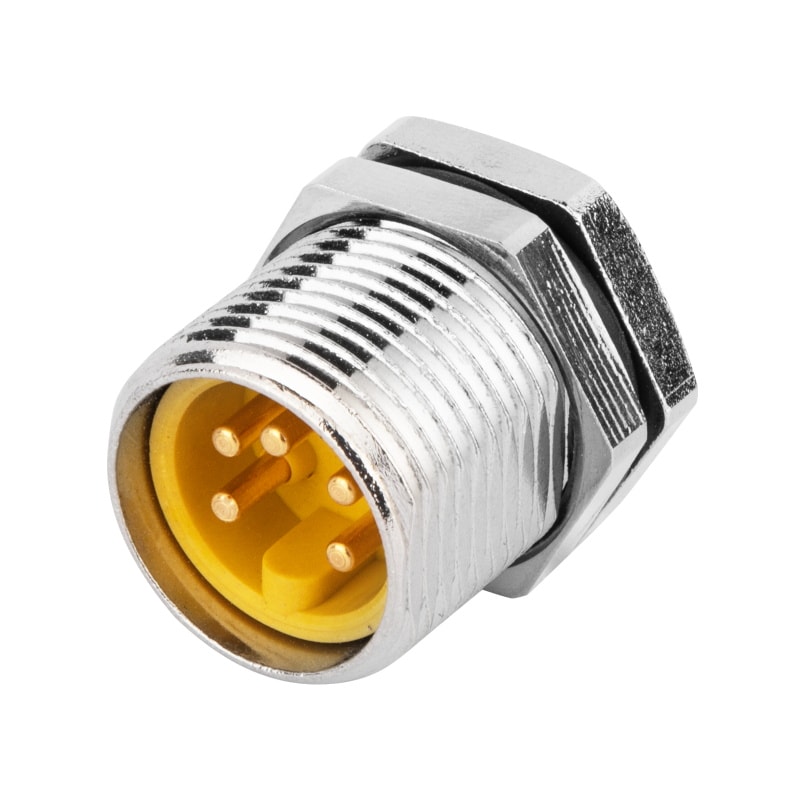
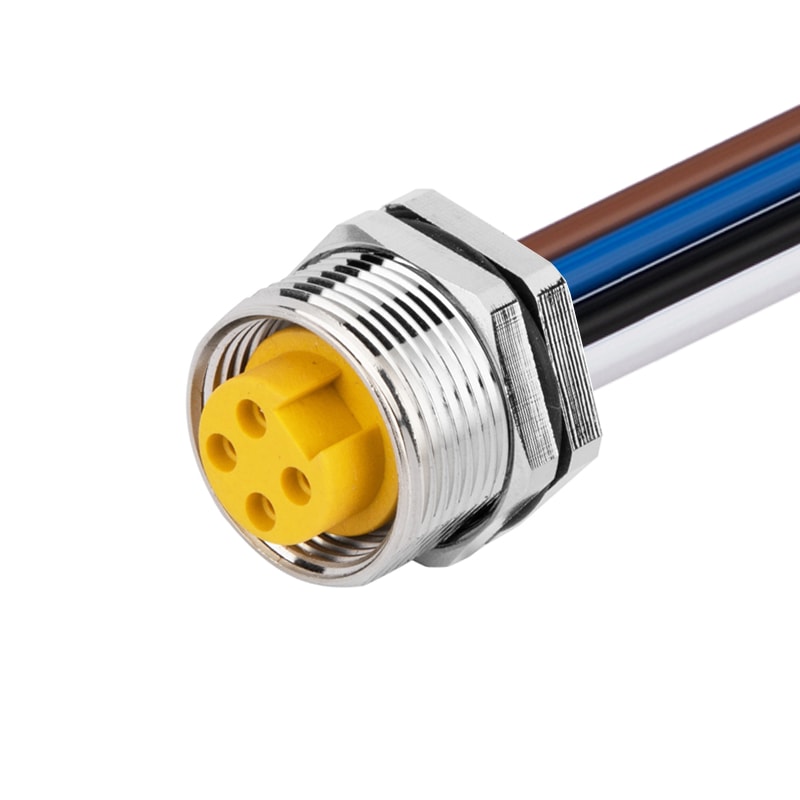
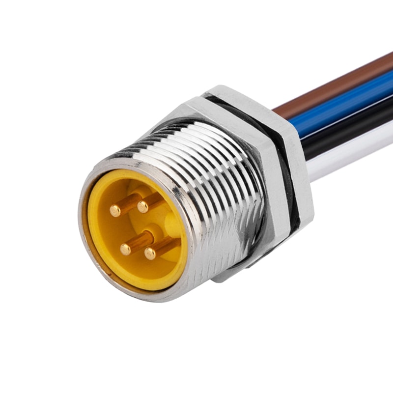
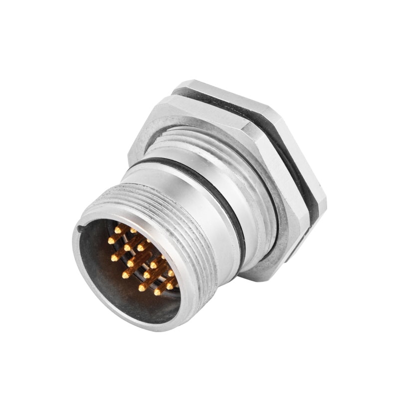
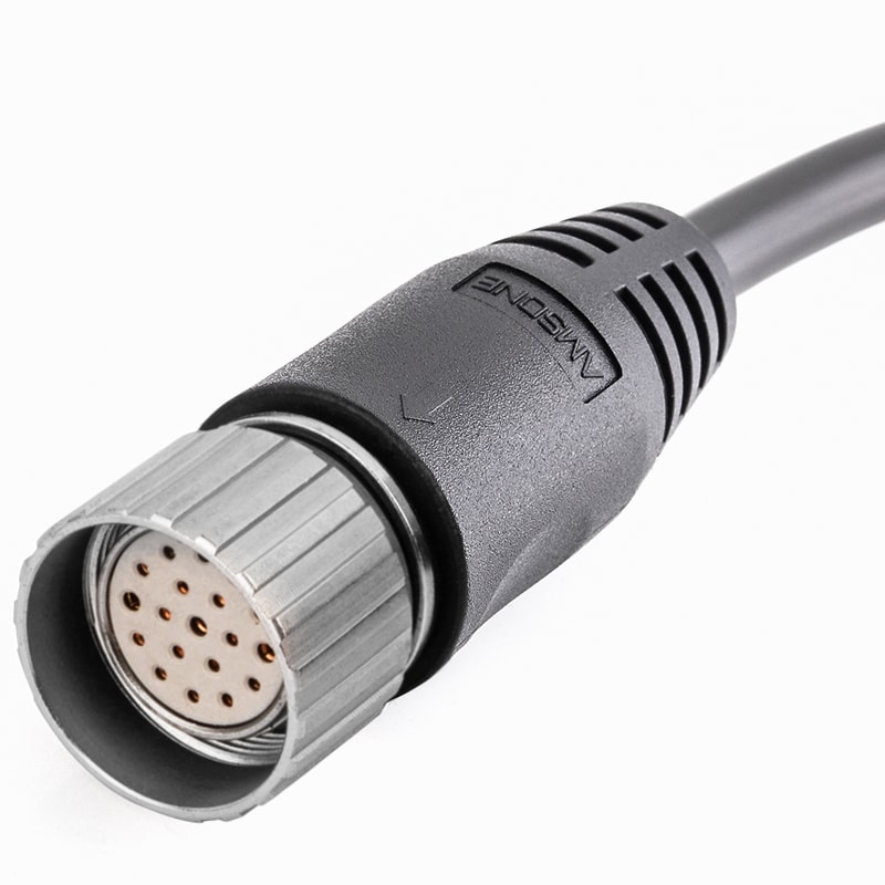
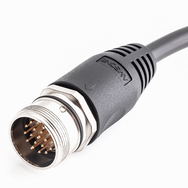
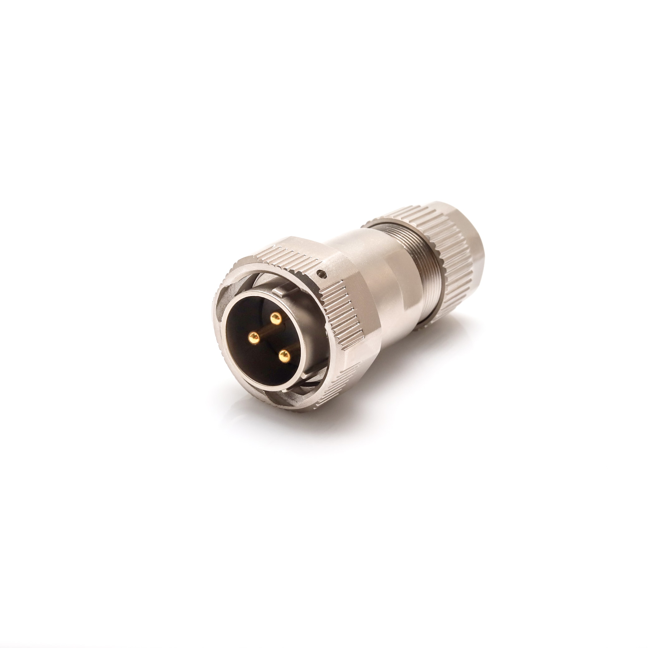
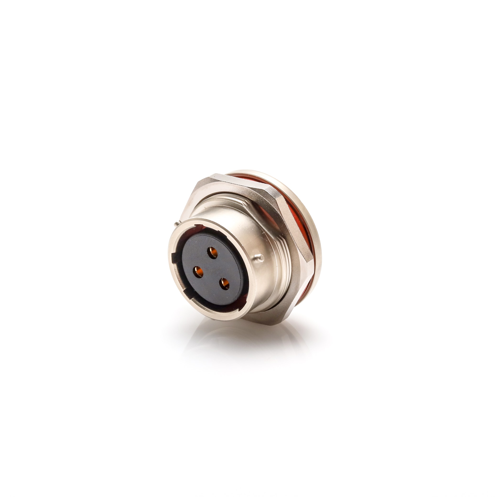
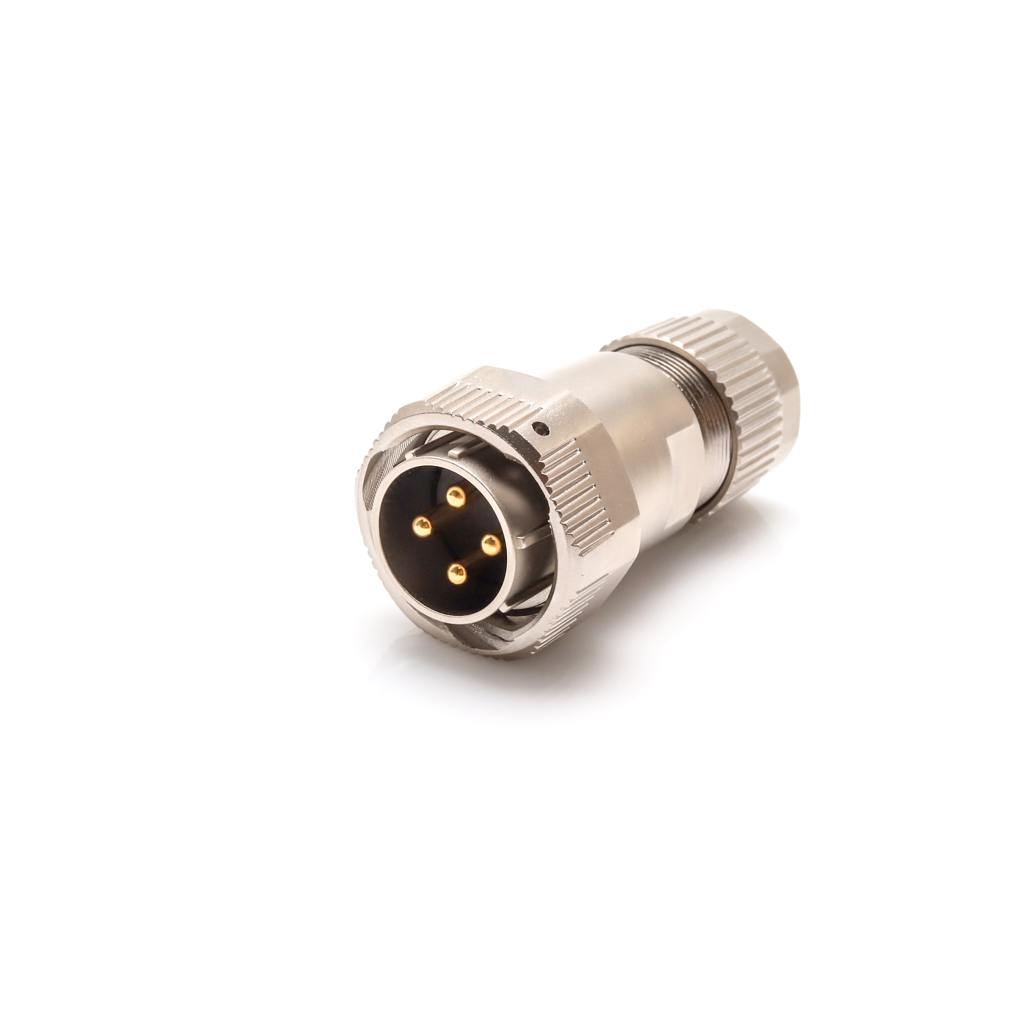
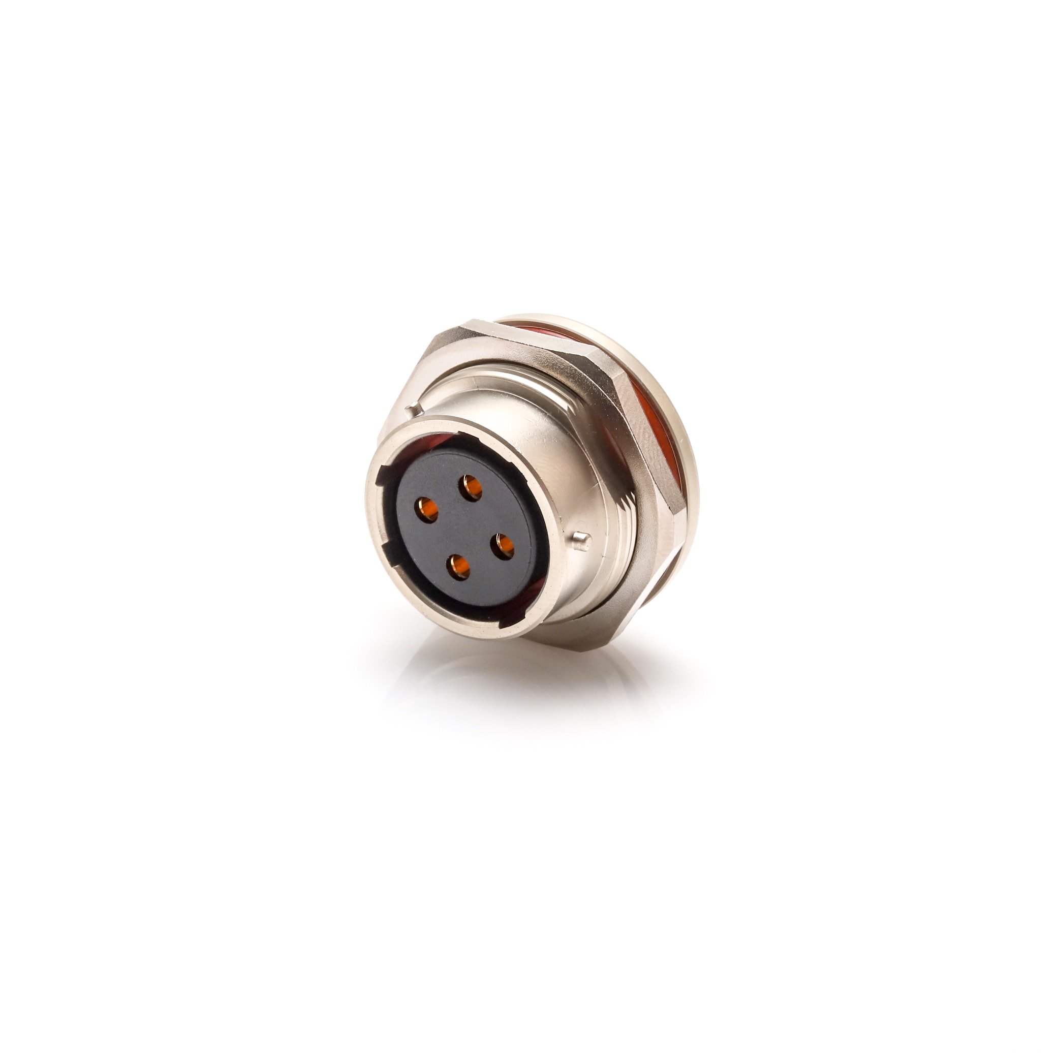
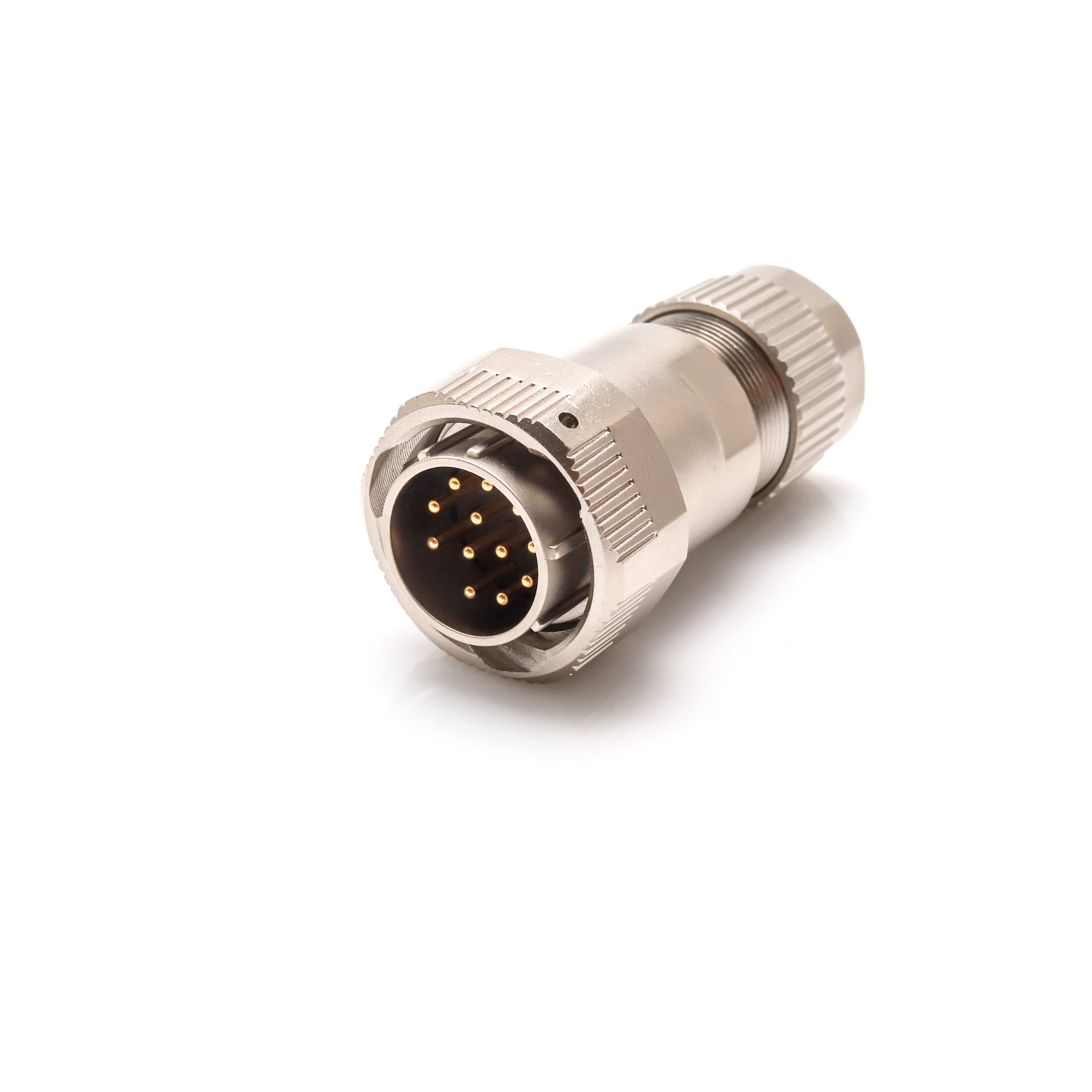
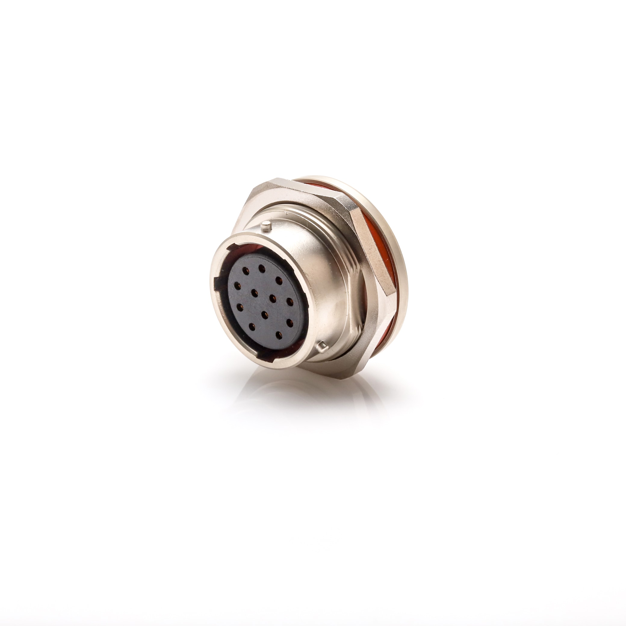
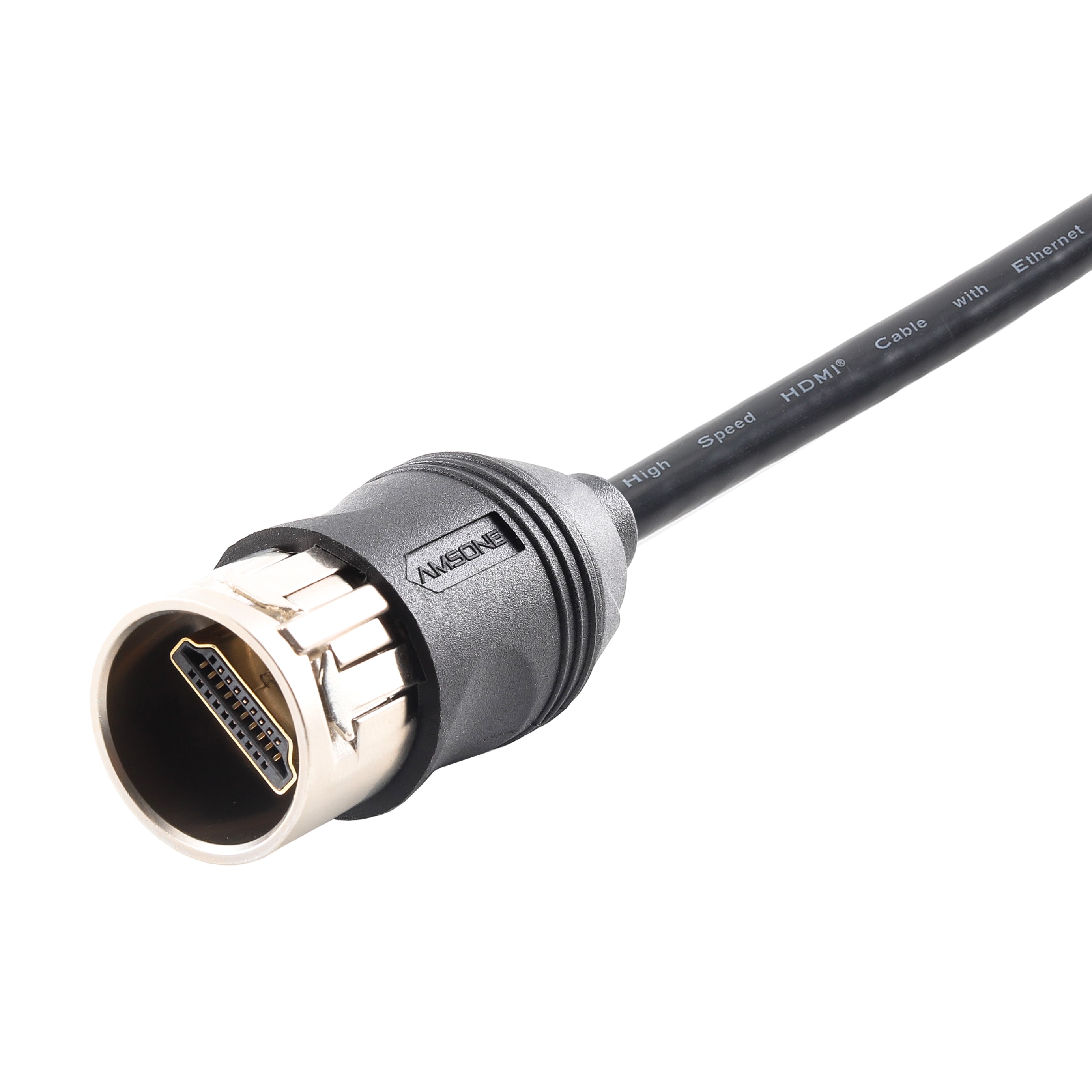
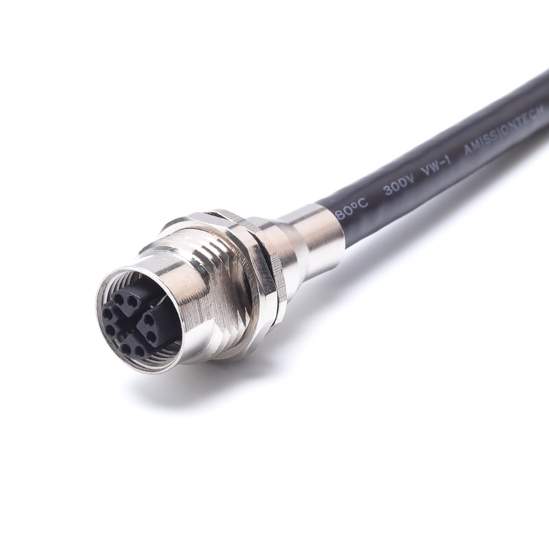
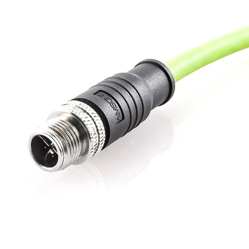
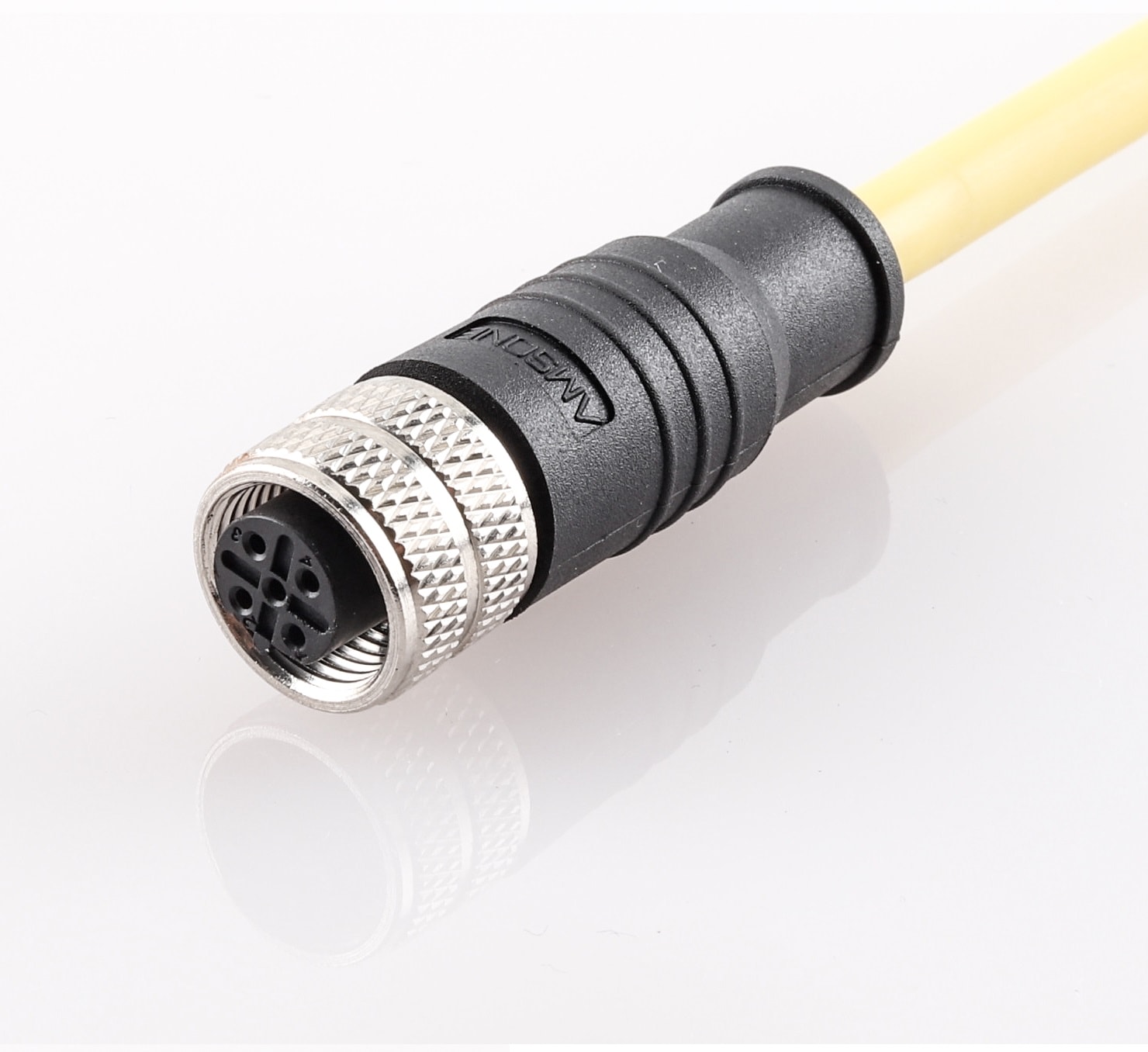
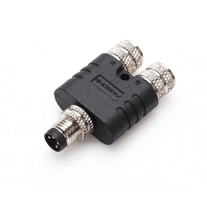
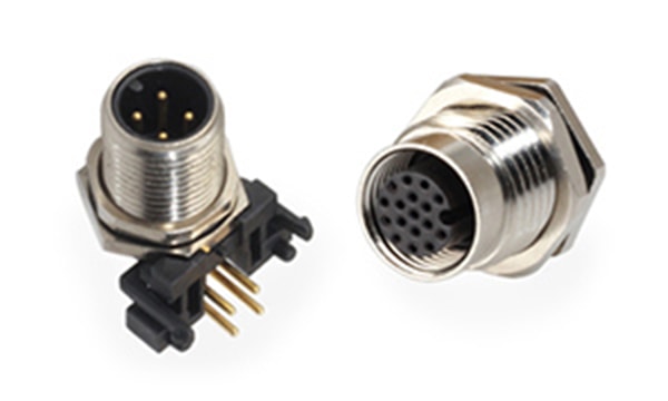
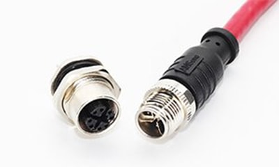
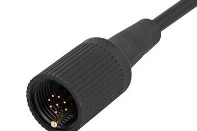
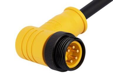
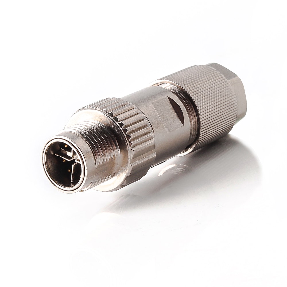
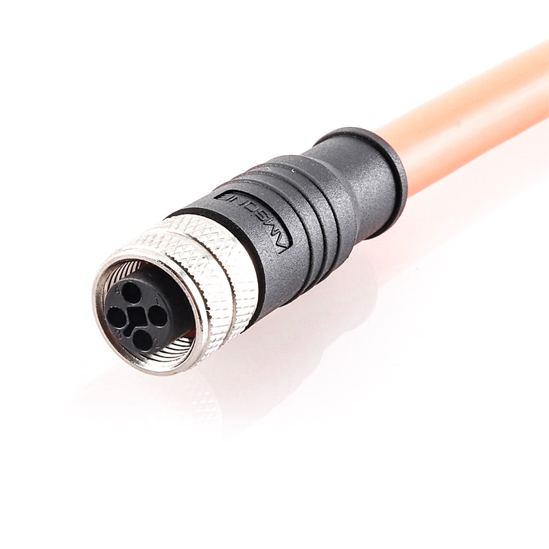
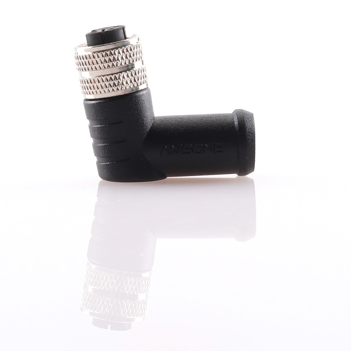
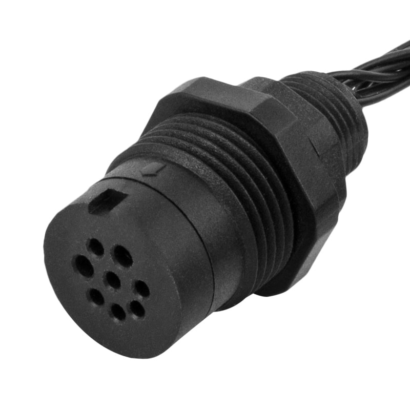
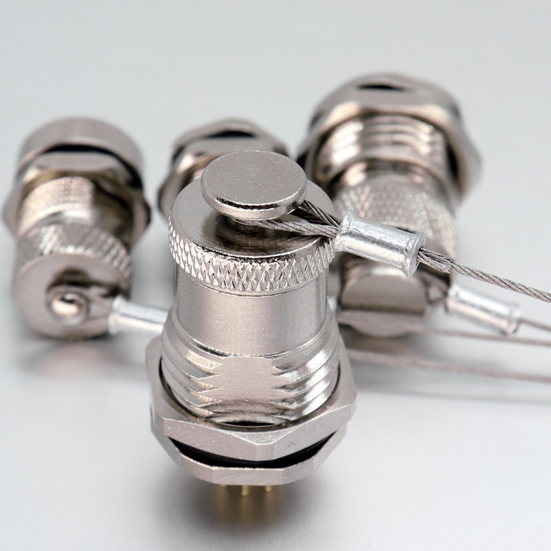
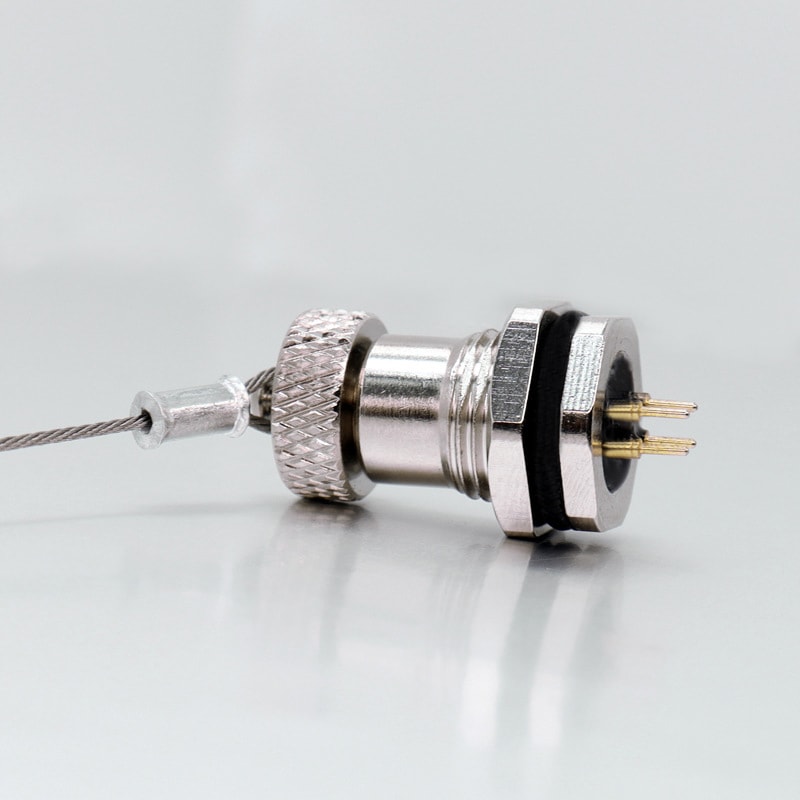
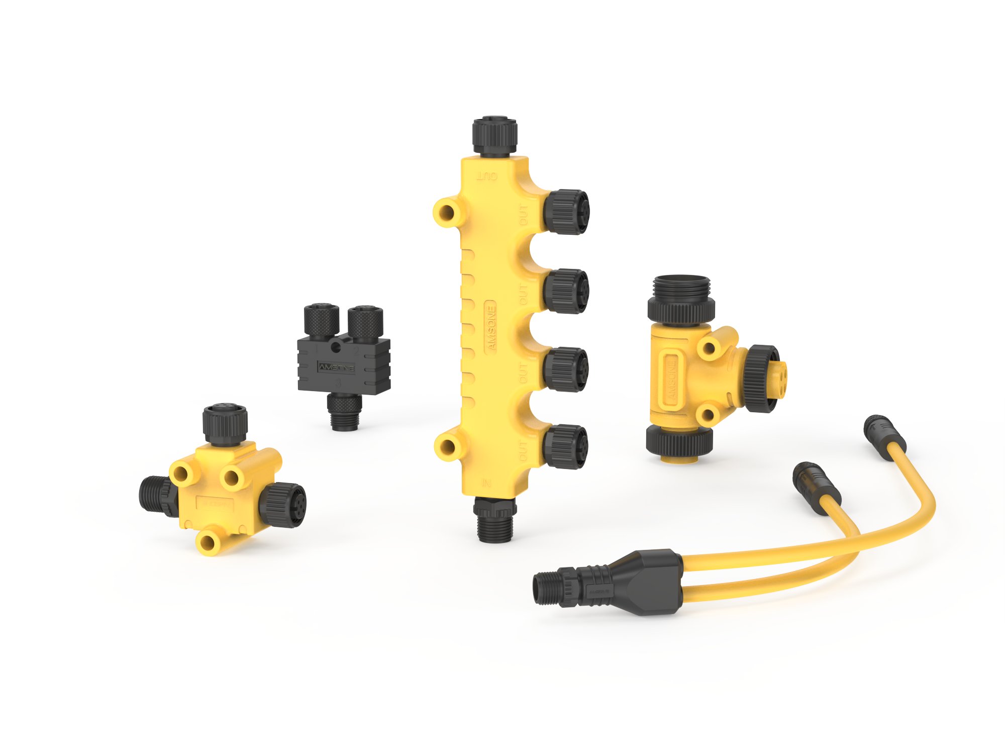
IO-Link uses standard M12, M8, or M5 connectors with pin assignments defined in the IEC 60947-5-2 specification. Cable lengths extend up to 20 meters between master and device using unshielded 3-conductor or 4-conductor industrial cable.
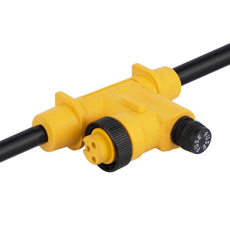
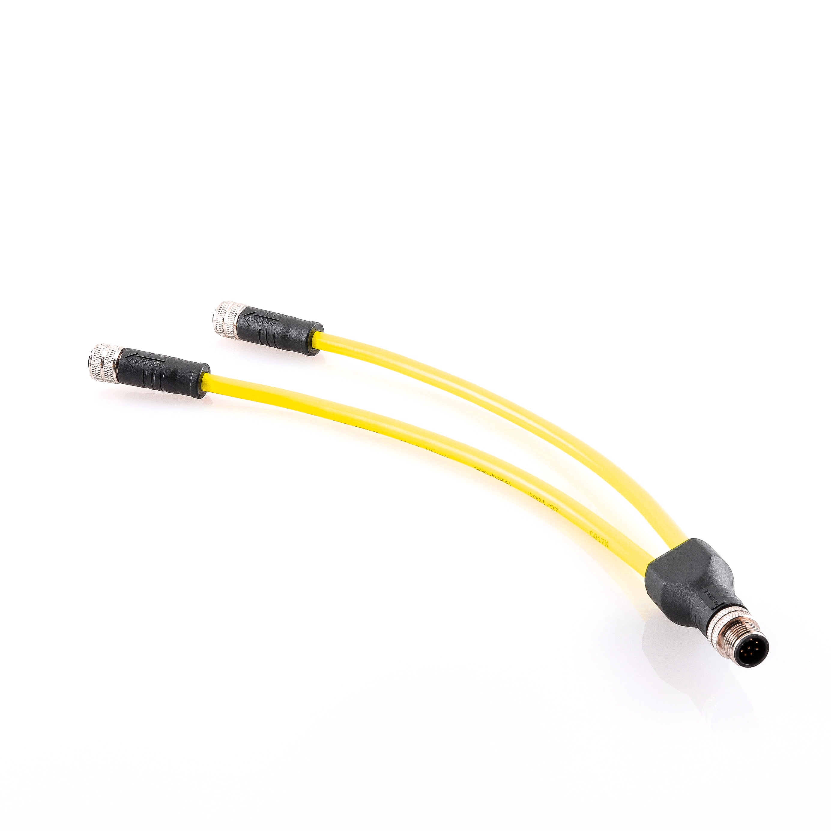
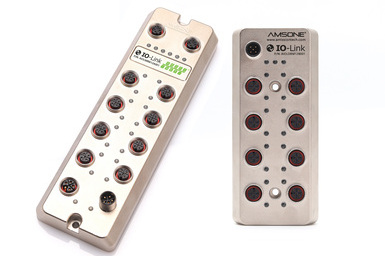
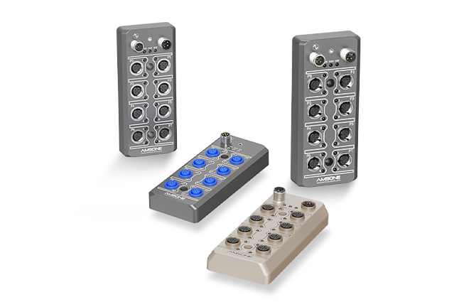
Passive distribution blocks and active IO-Link hubs expand the number of ports per master. Each channel segment maintains point-to-point integrity regardless of the distribution topology.
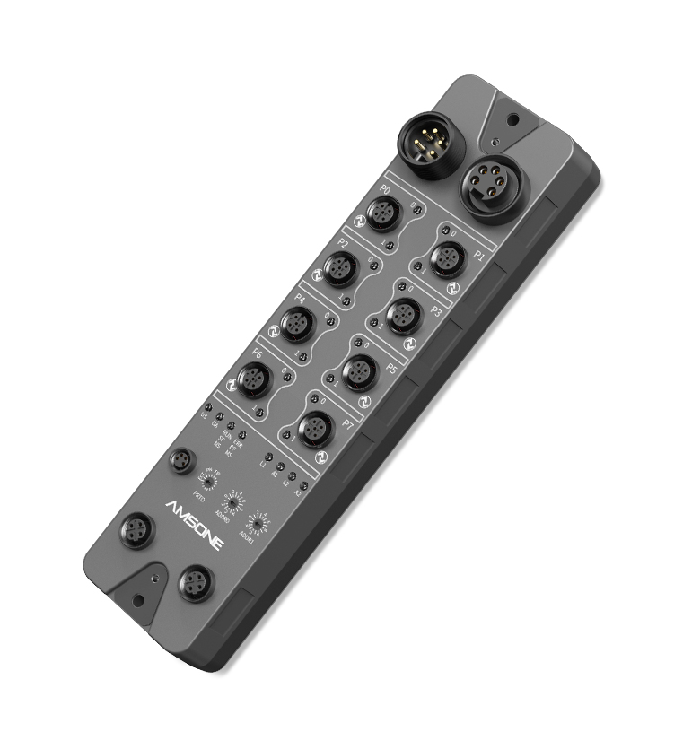
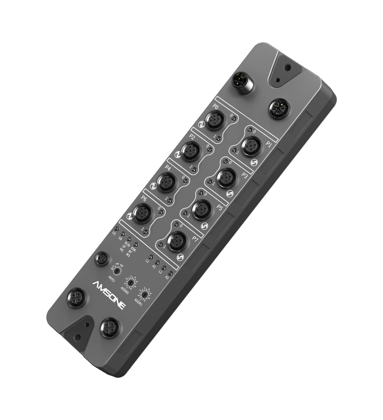
IO-Link masters mount inside control cabinets, on-machine in IP67-rated field housings, or directly on the machine frame. Field-mountable masters reduce cable runs from the cabinet to the machine, lowering material cost and simplifying cable management.
Hybrid masters combine IO-Link Class A ports with standard digital I/O points on a single module. This allows phased migration from conventional wiring to full IO-Link architecture without replacing the entire I/O infrastructure.
جدول مرجعي تقني B2B
|
معامل
|
COM1
|
COM2
|
COM3
|
|
معدل سرعة نقل البيانات
|
4.8 كيلو بايت
|
38.4 كيلو بايت
|
230.4 كيلو بايت
|
|
الحد الأدنى لوقت الدورة
|
مللي 4.8
|
مللي 2.3
|
مللي 0.4
|
|
Process Data Width
|
1-2 بايت
|
1-8 بايت
|
1-32 بايت
|
|
نوع الجهاز النموذجي
|
Inductive proximity
|
مرسلات الضغط
|
Laser distance sensors
|
|
أقصى طول للكابل
|
20 م
|
20 م
|
20 م
|
|
Data Storage Format
|
IODD (XML)
|
IODD (XML)
|
IODD (XML)
|
|
Pin 2 Function
|
Digital I/O (SIO)
|
Serial Data (C/Q)
|
Serial Data (C/Q)
|
|
Pin 4 Function
|
المدخلات الرقمية
|
المدخلات الرقمية
|
المدخلات الرقمية
|
الأسئلة الشائعة
Does IO-Link require special cabling or connectors?
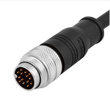
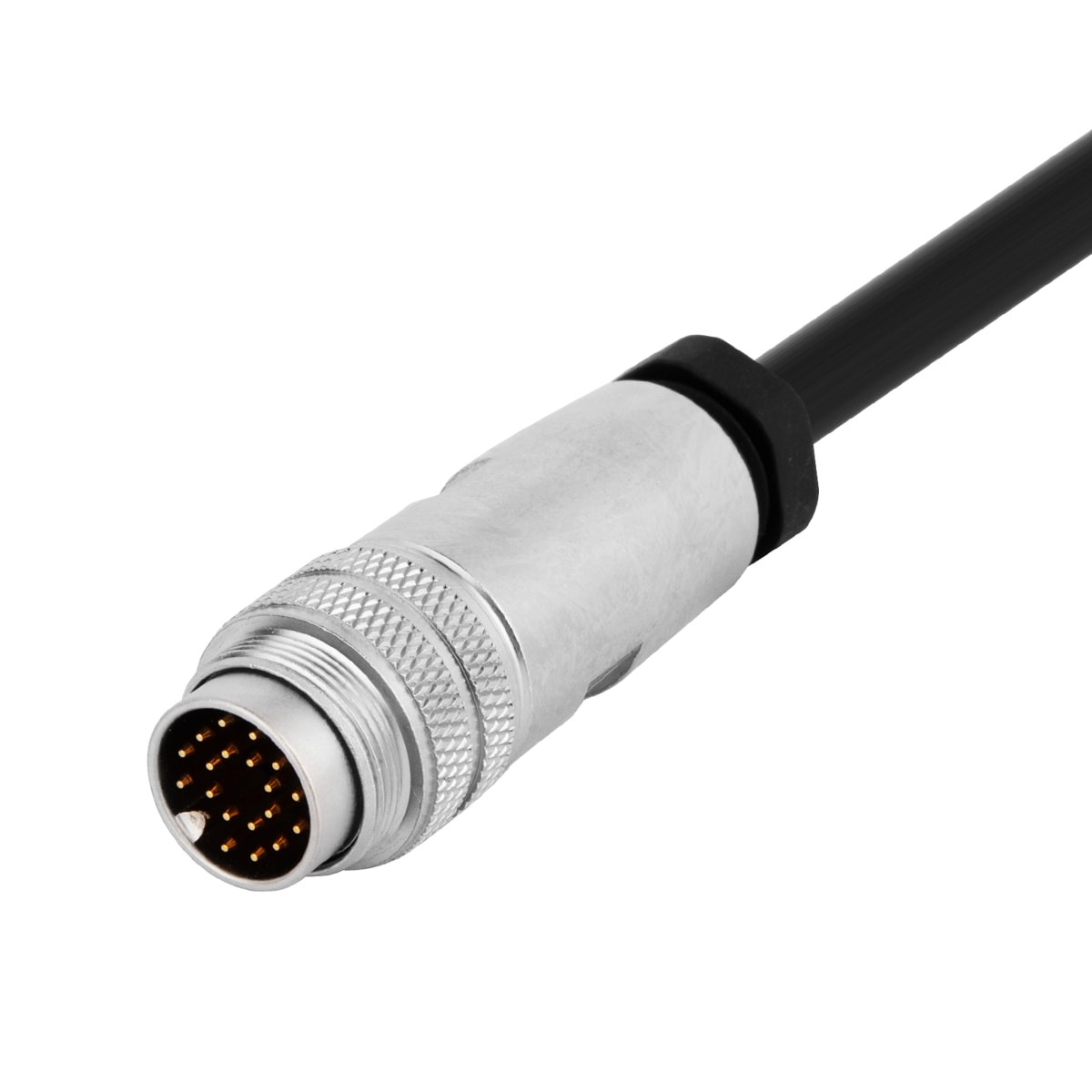
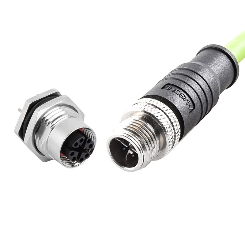
IO-Link operates over standard unshielded 3-conductor industrial cable with M12 connectors conforming to IEC 61076-2-101. No proprietary cable assemblies or specialized connectors are required.
Existing sensor wiring installations can often be reused when upgrading from discrete I/O to IO-Link. The cable must meet basic signal integrity requirements for the selected communication speed.
Can IO-Link work with existing PLC systems?
IO-Link masters interface with PLCs through standard fieldbus protocols including PROFINET, EtherNet/IP, EtherCAT, and Modbus TCP. The PLC reads IO-Link process data through its native I/O mapping mechanism without custom function blocks or special firmware.
Most major PLC platforms offer integrated IO-Link configuration tools. These tools handle commissioning and parameter management within the standard engineering environment.
What is the difference between IO-Link and traditional 4-20 mA analog sensors?
Traditional 4-20 mA sensors transmit only a single analog process value over two dedicated conductors. IO-Link devices deliver primary process data, secondary measurements, and diagnostic information simultaneously through digital communication.
Parameter configuration on analog sensors requires physical access for trimpot adjustment or DIP switch setting. IO-Link sensors accept remote parameter writes through the engineering tool, the PLC, or the HMI without technician access to the device.
How does IO-Link handle device replacement during maintenance?
The IO-Link master stores a complete backup of the device parameter set in non-volatile memory. When an identical replacement device connects to the same port, the master downloads stored parameters and resumes operation within seconds.
This automated restore process eliminates manual configuration steps during field service. It removes the need for a programming device at the machine and ensures parameter consistency after every replacement event.
خاتمة
IO-Link provides a standardized digital interface that simplifies sensor integration, reduces wiring cost, and delivers actionable diagnostic data for predictive maintenance. The protocol's backward compatibility with SIO mode supports phased migration from legacy I/O without disrupting existing production assets.
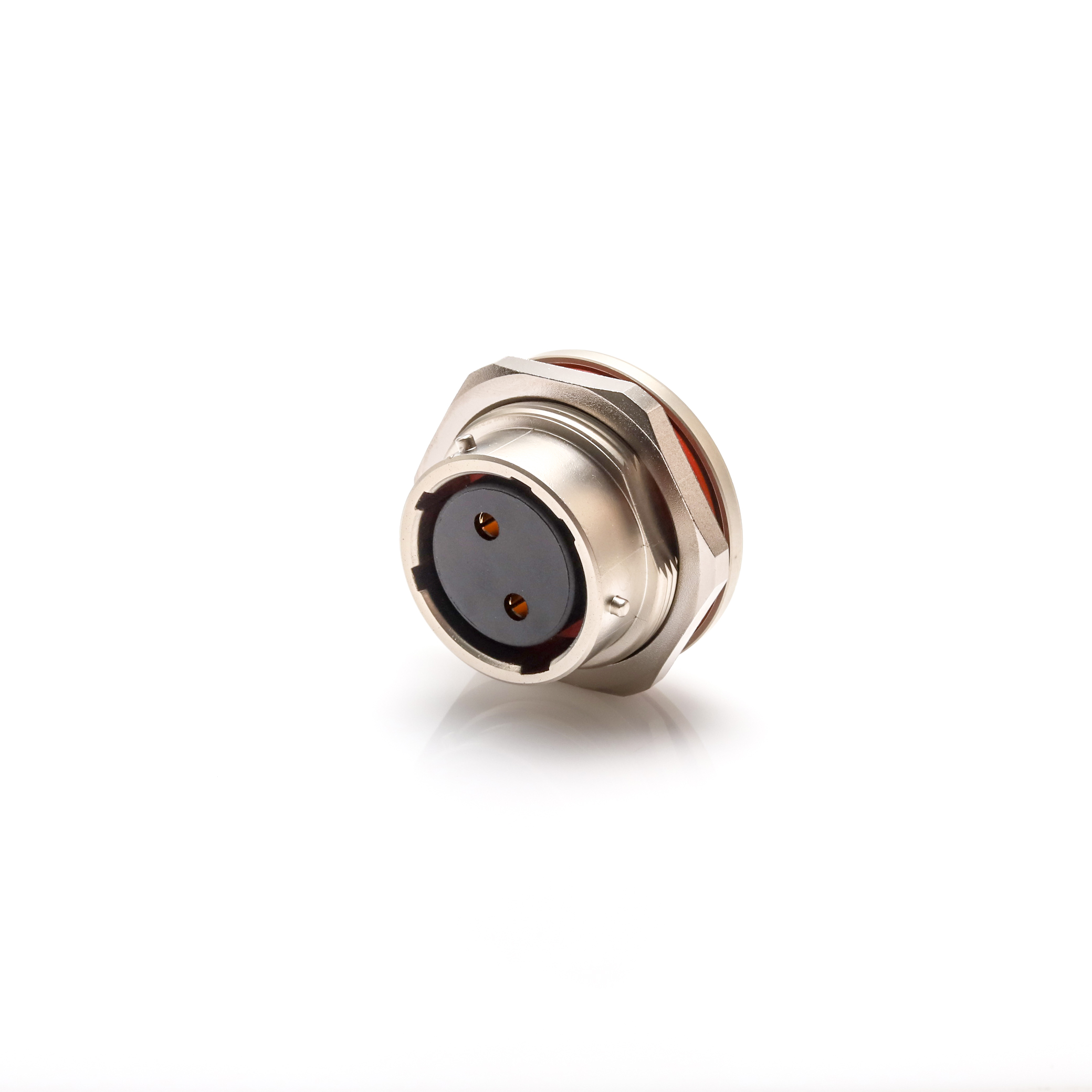
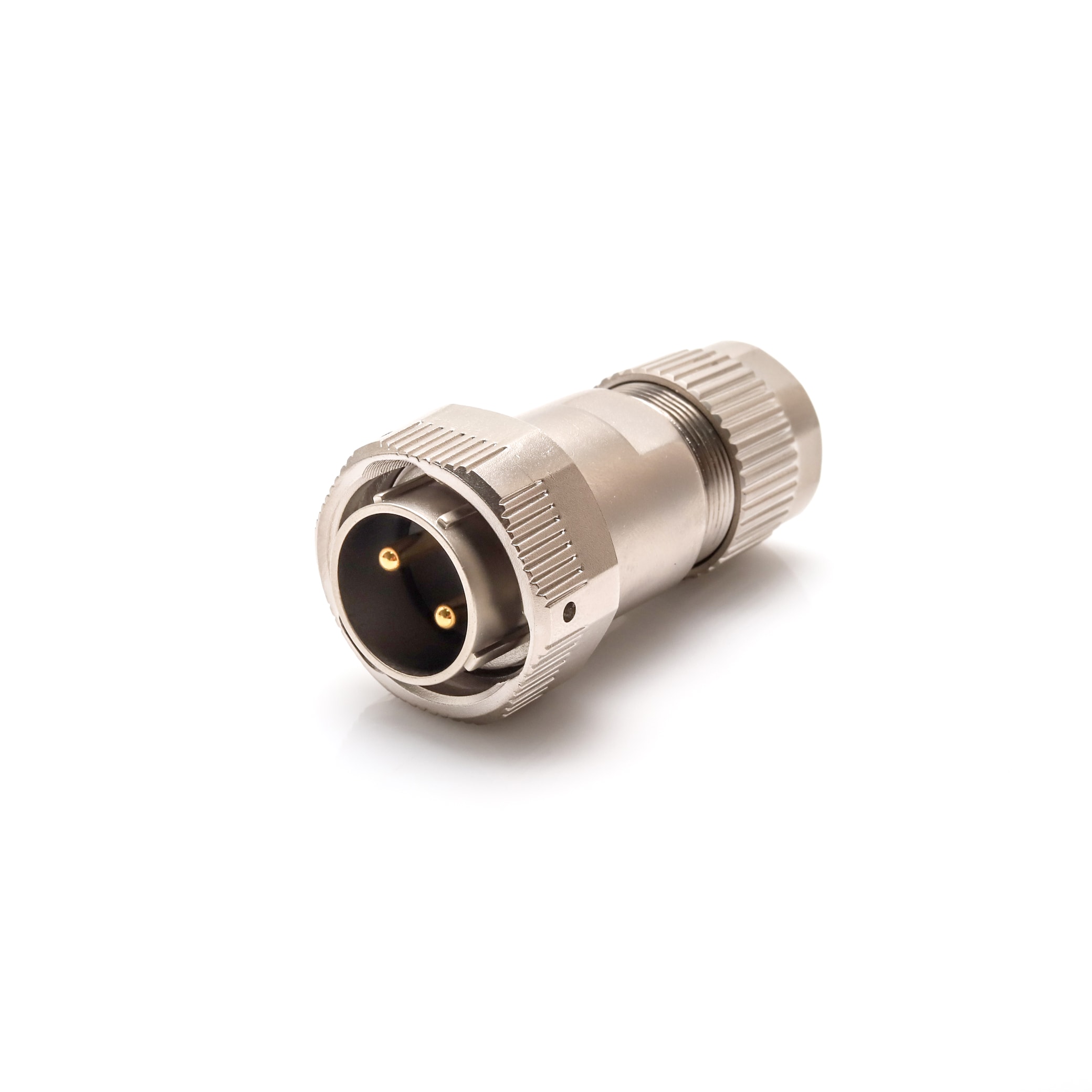
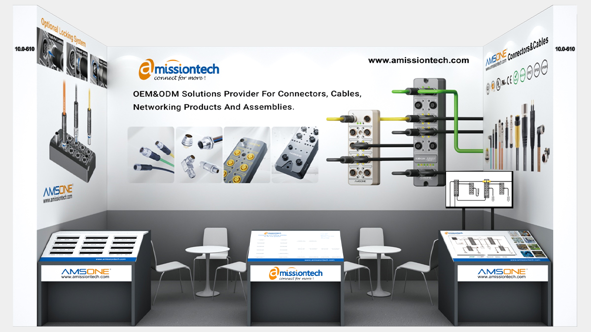
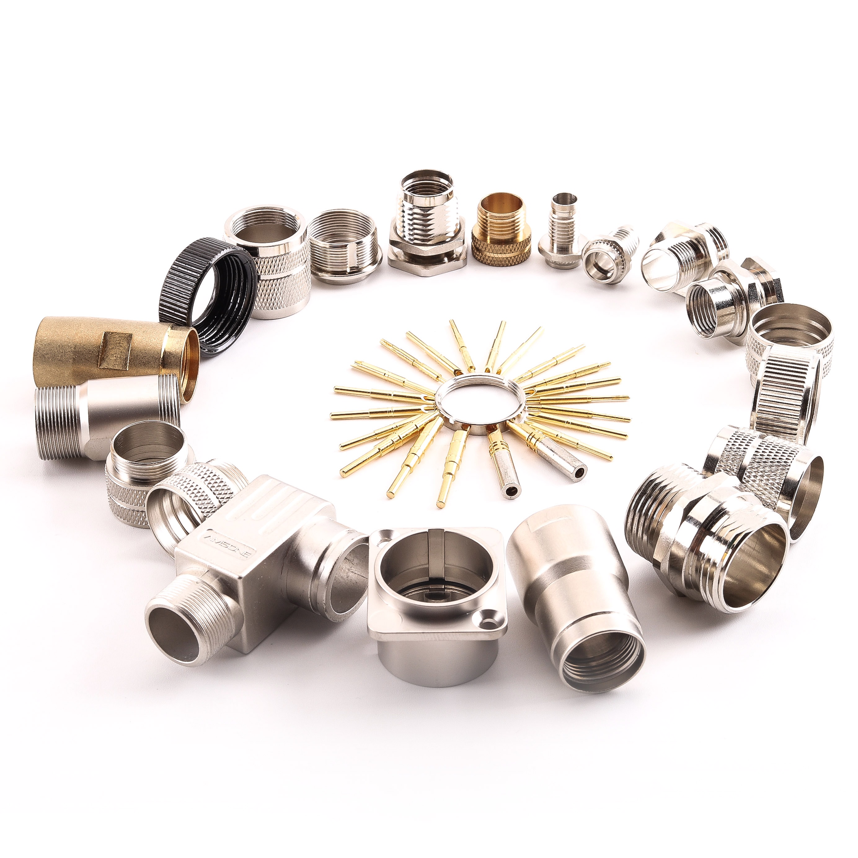
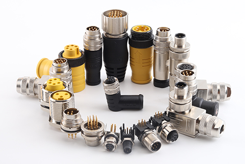
As a manufacturer with 10-plus years of experience in industrial connectors and cable harnesses, Amissiontech supplies IO-Link-ready connectivity components meeting IEC 61131-9 requirements.
Request a Rapid Sourcing Quote from Amissiontech for pre-assembled M12 IO-Link cable assemblies in standard and custom lengths. Contact the Amissiontech Engineering Team for Free Custom Design Support on hybrid connector solutions combining power and IO-Link communication in a single overmolded cable assembly.