Modbus and IO-Link are both industrial communication protocols, but they serve fundamentally different layers of the automation architecture. Modbus operates as a fieldbus protocol connecting controllers, HMIs, and intelligent devices. IO-Link functions as a device-level point-to-point protocol connecting individual IO-Link sensor s and actuators to a master gateway.
Understanding the distinction between these two protocols is essential for specifying the correct communication architecture in industrial automation projects. Each protocol addresses a distinct set of engineering requirements and occupies a different position in the automation pyramid.
Protocol Architecture and Communication Model
Modbus Communication Topology
Modbus uses a master-slave architecture over multi-drop serial lines or TCP/IP Ethernet networks. A single Modbus master communicates with up to 247 slave devices on an RS-485 bus segment. Each slave device requires a unique address configured through DIP switches or software settings.
Modbus RTU transmits binary data frames over RS-485 or RS-232 at baud rates from 1.2 kbps to 115.2 kbps. Modbus TCP encapsulates the same application-layer protocol in TCP/IP packets for transmission over standard Ethernet infrastructure at 10/100 Mbps.
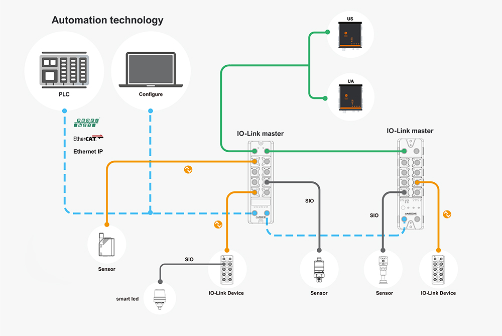
IO-Link Communication Topology
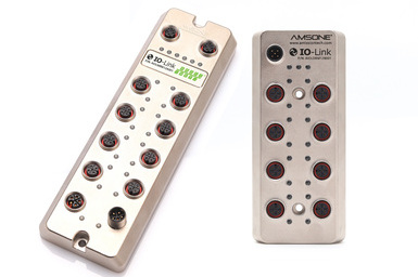
IO-Link uses a strict point-to-point topology between a master port and a single device. Each master port connects to exactly one sensor or actuator through a dedicated cable. There is no device addressing and no bus arbitration because the communication channel is exclusive.
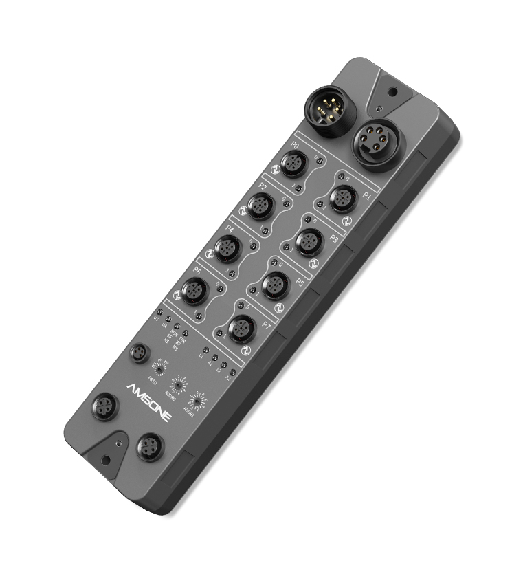
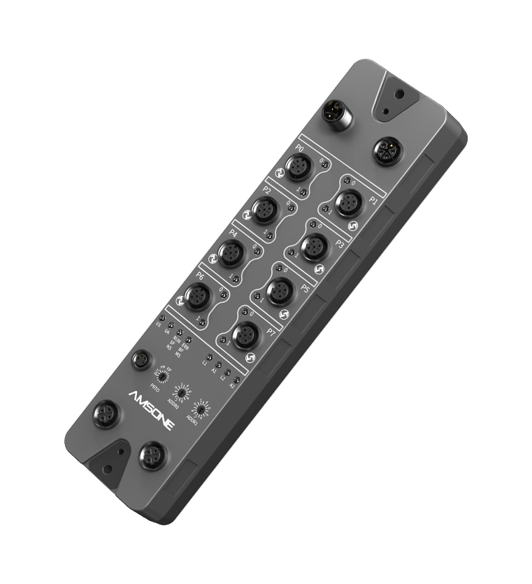
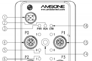
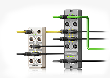
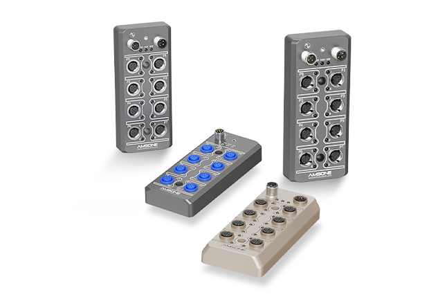
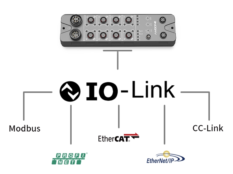
The master acts as a gateway between the IO-Link device and the higher-level fieldbus network. Data from multiple IO-Link devices aggregates at the master and transfers to the PLC through PROFINET, EtherNet/IP, EtherCAT, or Modbus TCP.
Data Exchange and Payload Characteristics
Modbus handles register-based data exchange organized as coils, discrete inputs, holding registers, and input registers. Each register holds a 16-bit value representing process variables, setpoints, or status flags. Read and write operations address specific register ranges through function codes embedded in the protocol frame.
IO-Link transmits process data cyclically in frames of 1 to 32 bytes depending on the device complexity. The frame carries pre-structured data defined by the IODD device description file. Unlike Modbus, IO-Link data content is self-describing because the IODD file maps every byte position to a named variable with units, range, and data type.
Parameter Configuration and Device Management
Modbus Parameter Handling
Modbus provides no standardized mechanism for device parameter storage or automatic configuration. Each device manufacturer defines its own register map for parameter access. Engineers must consult device-specific documentation to locate the correct register addresses for each configurable setting.
Parameter backup and restore functions require custom PLC logic or dedicated commissioning software. Device replacement involves manual re-entry of configuration values through an HMI or engineering tool.
IO-Link Parameter Handling
IO-Link masters automatically store device parameter sets as backup copies. The IODD file defines every parameter name, data type, default value, and acceptable range in a standardized XML format that any engineering tool can parse.
When a failed IO-Link device is replaced with an identical unit, the master downloads the stored parameters automatically. This removes manual configuration from the replacement workflow and ensures parameter consistency without operator intervention.
Diagnostic Capability Comparison
Modbus provides limited built-in diagnostic functionality. Error detection relies on CRC checks within each data frame and basic exception codes returned by slave devices. There is no standard mechanism for devices to report health status, operating hours, or predictive maintenance data.
IO-Link embeds diagnostic data as a third communication channel alongside process and service data. Devices continuously transmit health indicators, operating counters, temperature readings, and error flags. The PLC accesses this diagnostic stream through the same fieldbus interface that carries process data, requiring no additional wiring or modules.
Deployment and Wiring Considerations
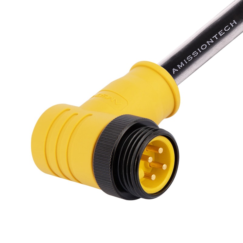
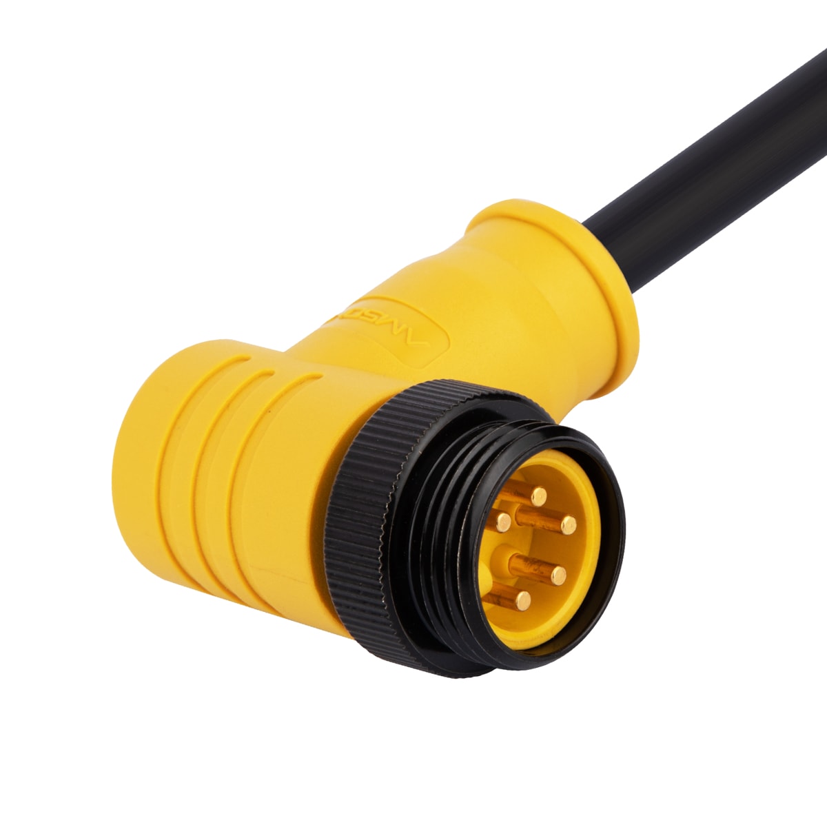
Modbus RTU installations use RS-485 twisted-pair cabling with termination resistors at both ends of the bus segment. Cable lengths extend to 1,200 meters at lower baud rates. Multi-drop wiring reduces cable count for distributed installations but introduces potential single points of failure and signal reflection issues.
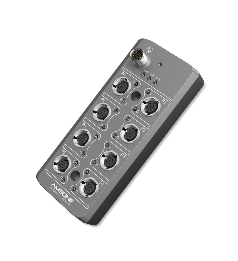
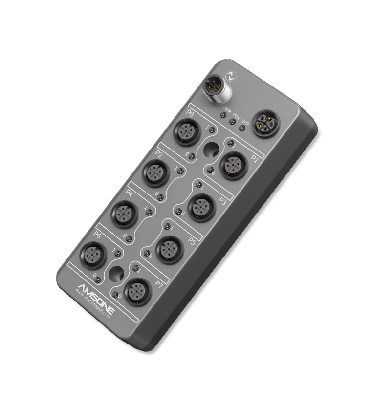
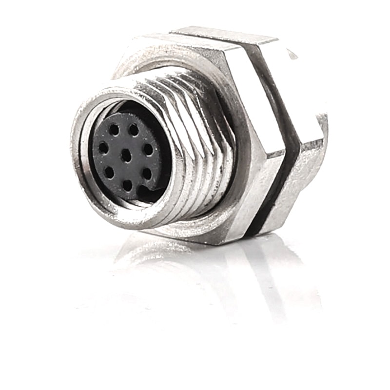
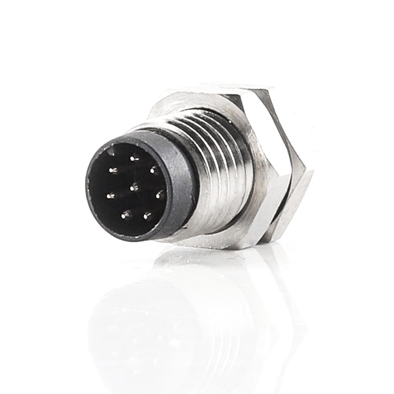
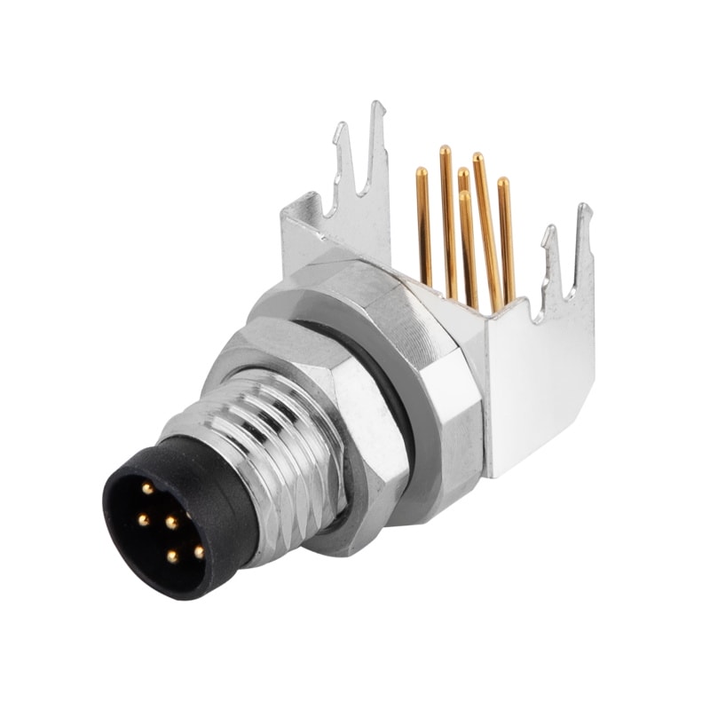
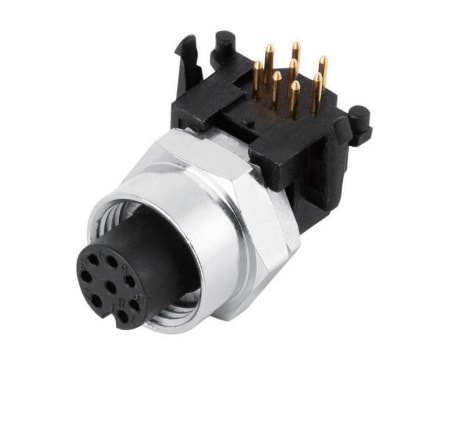
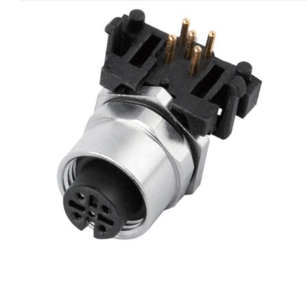
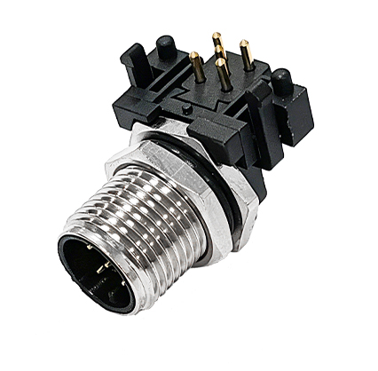
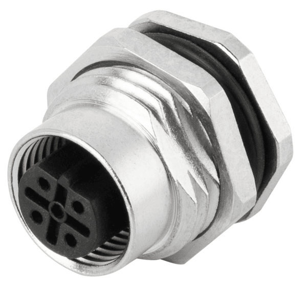
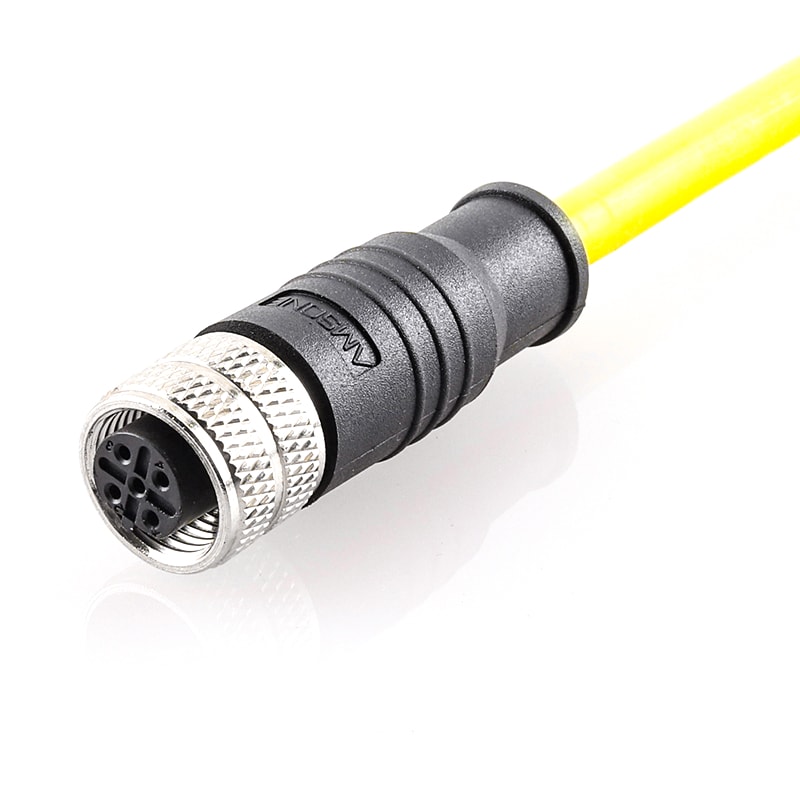
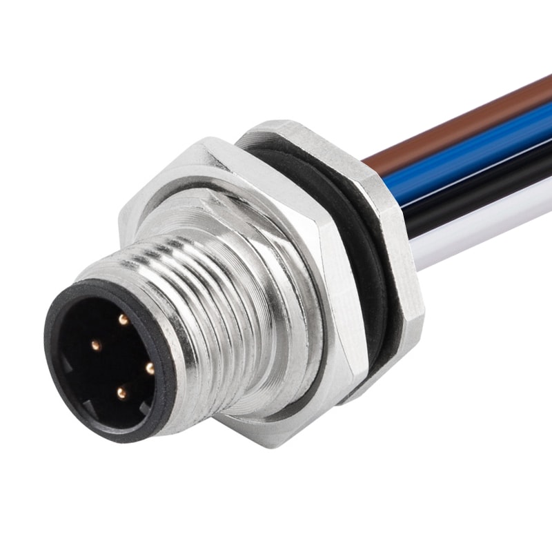
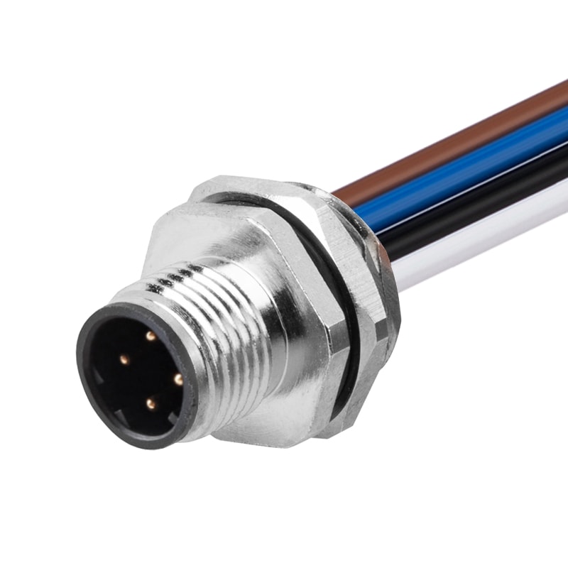
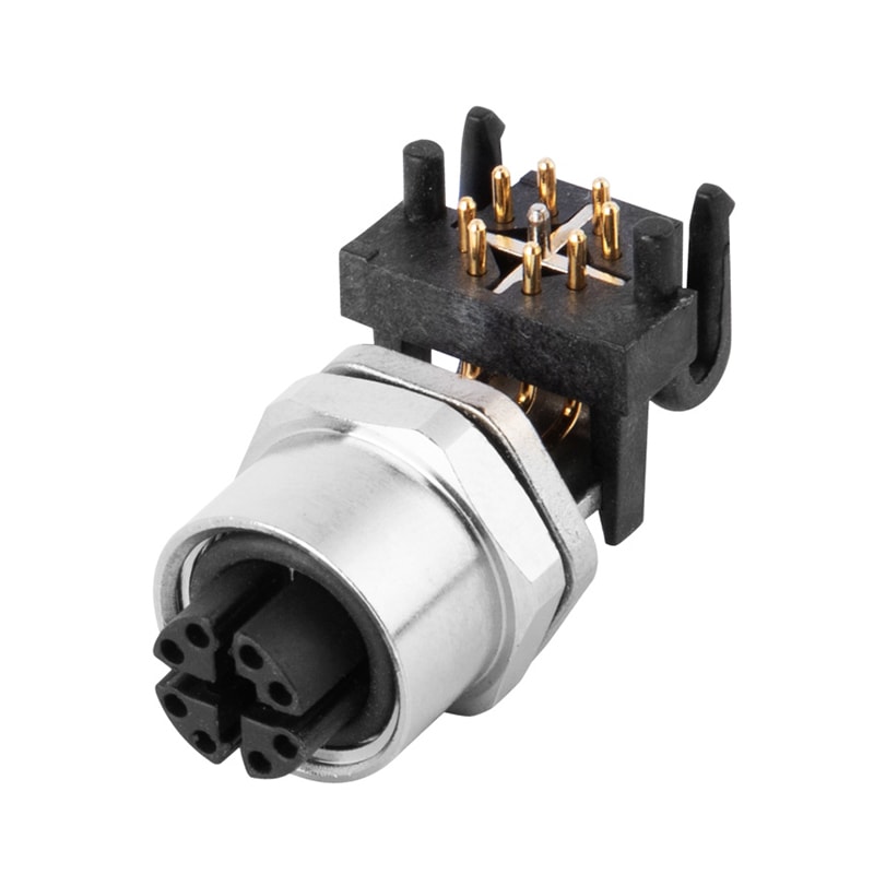
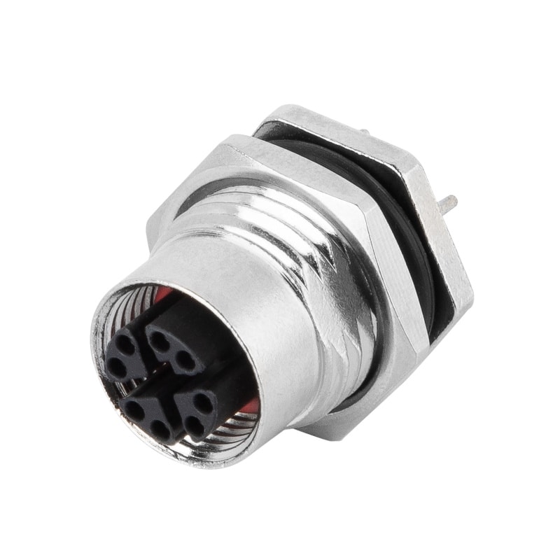
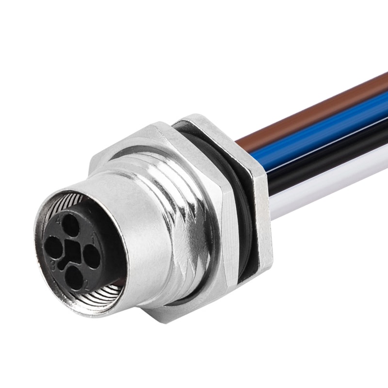
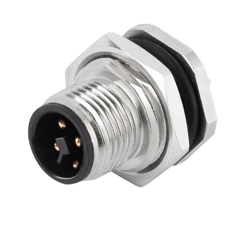
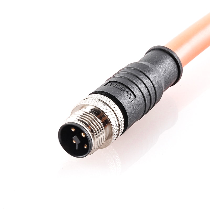
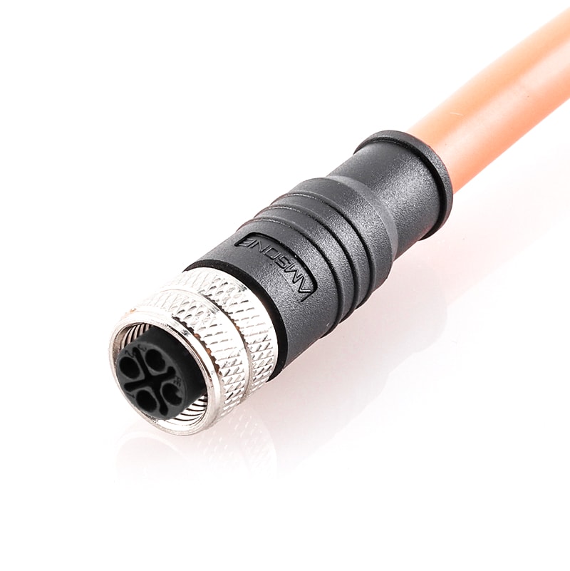
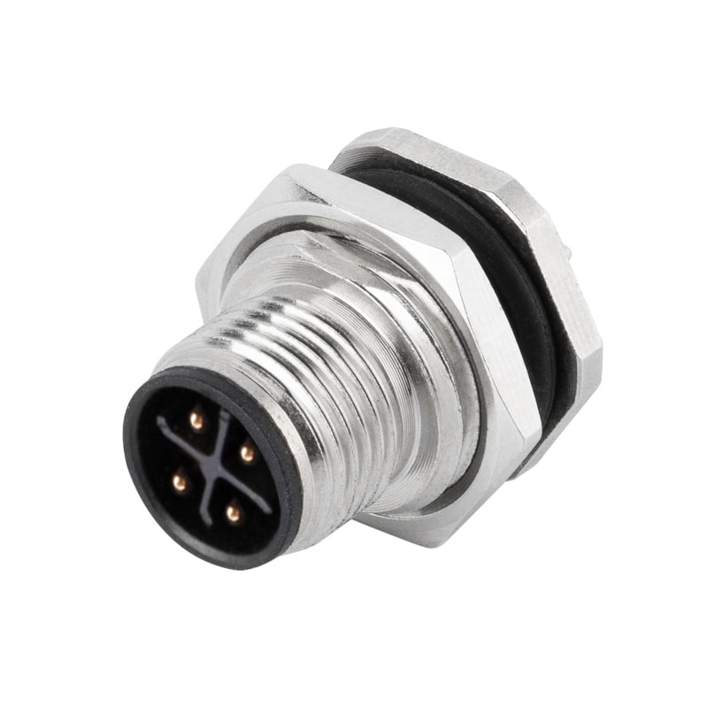
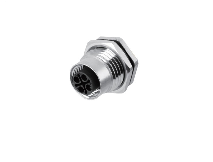
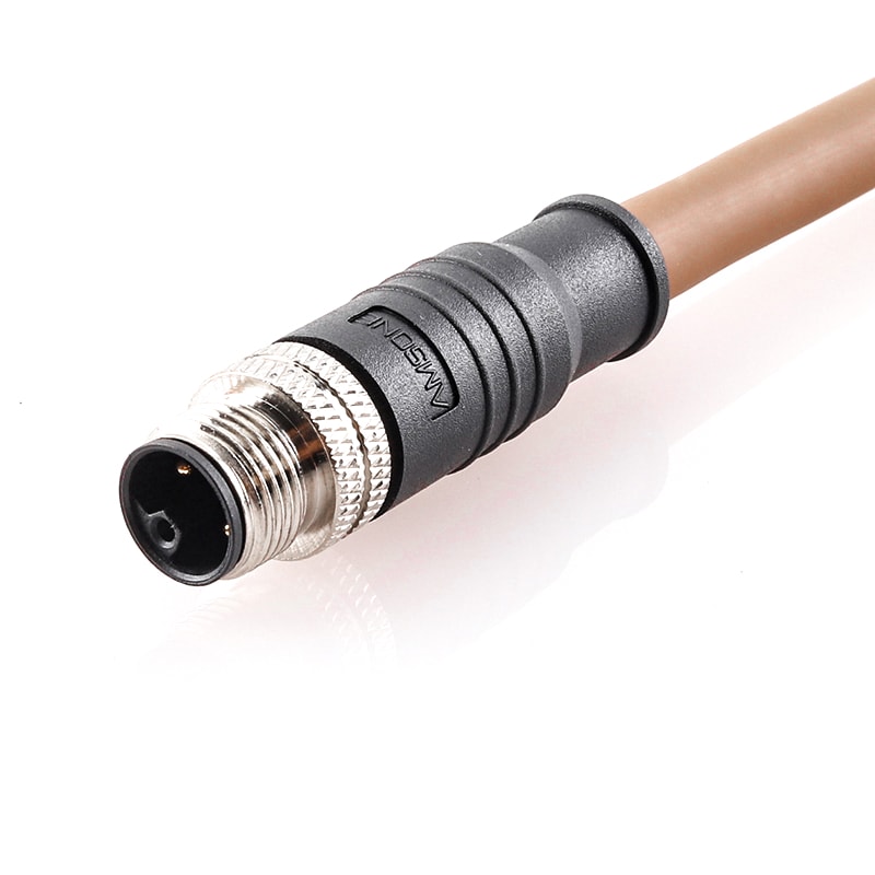
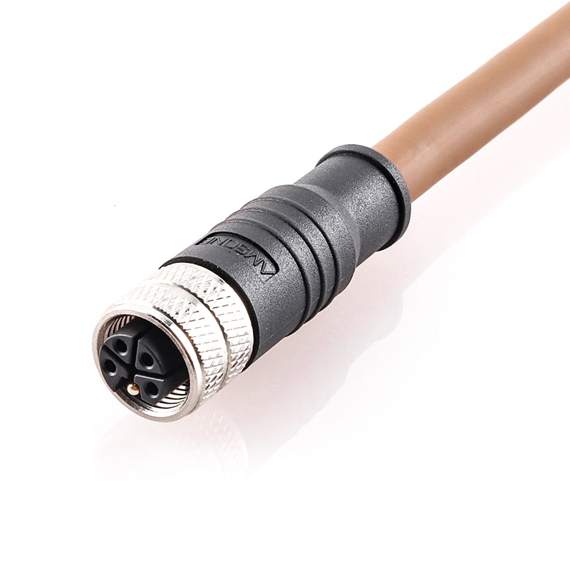
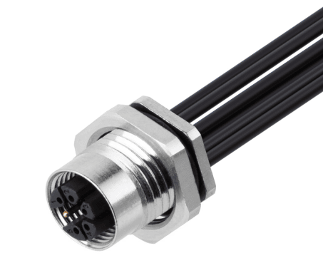
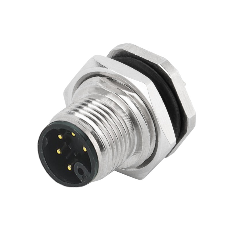
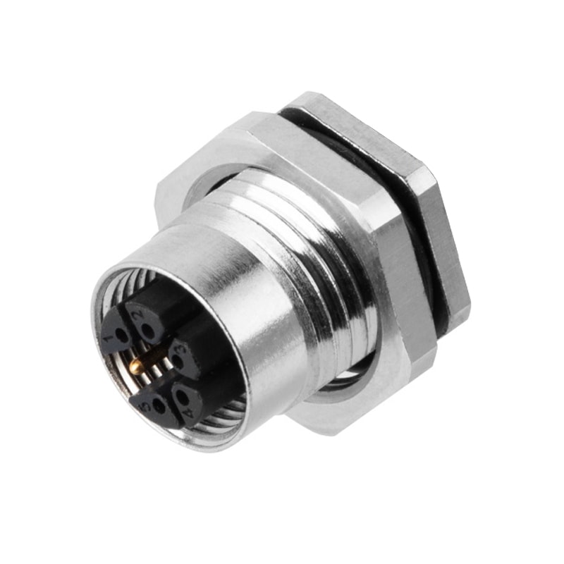
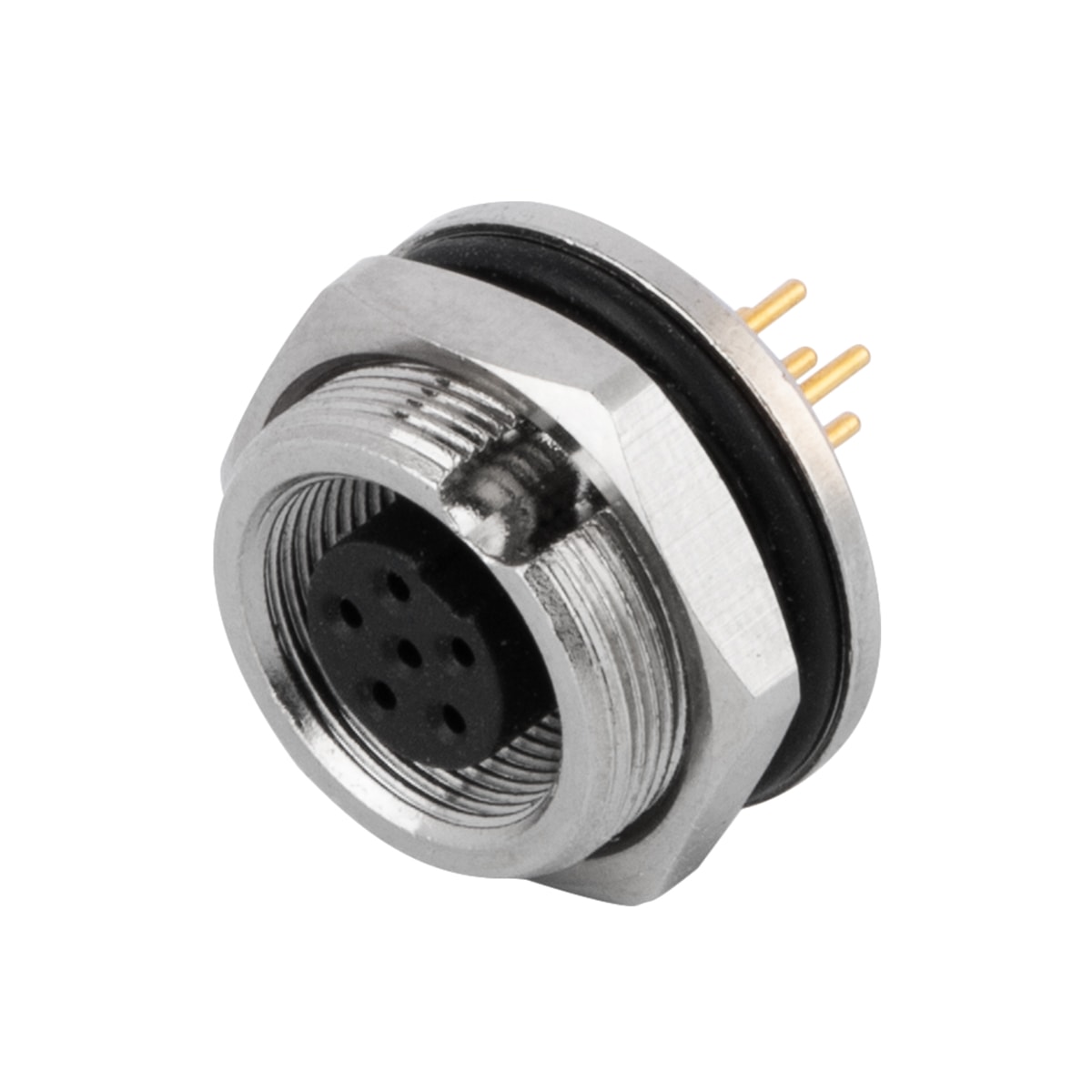
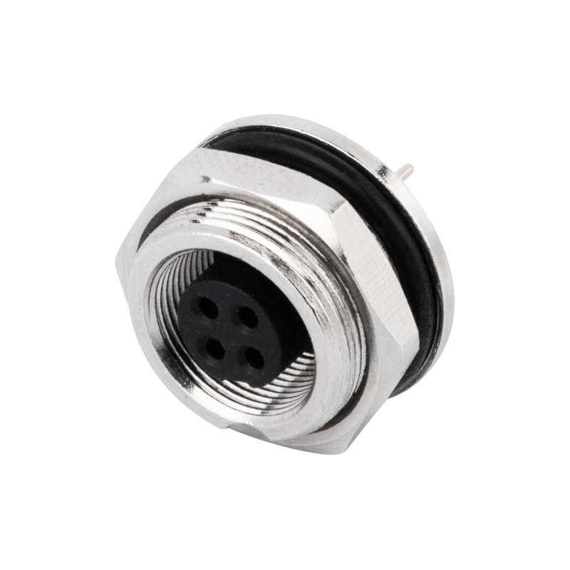
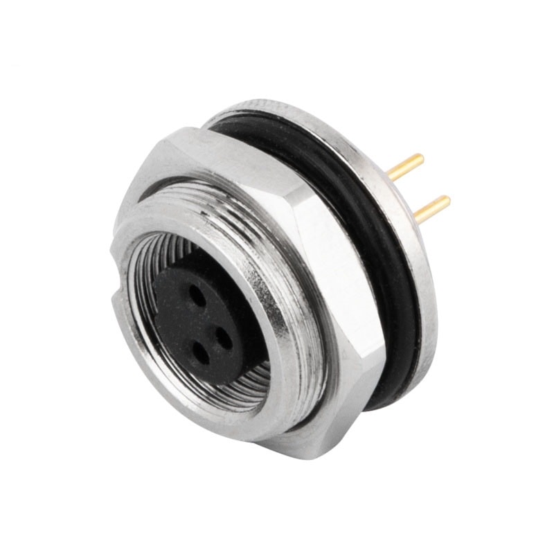
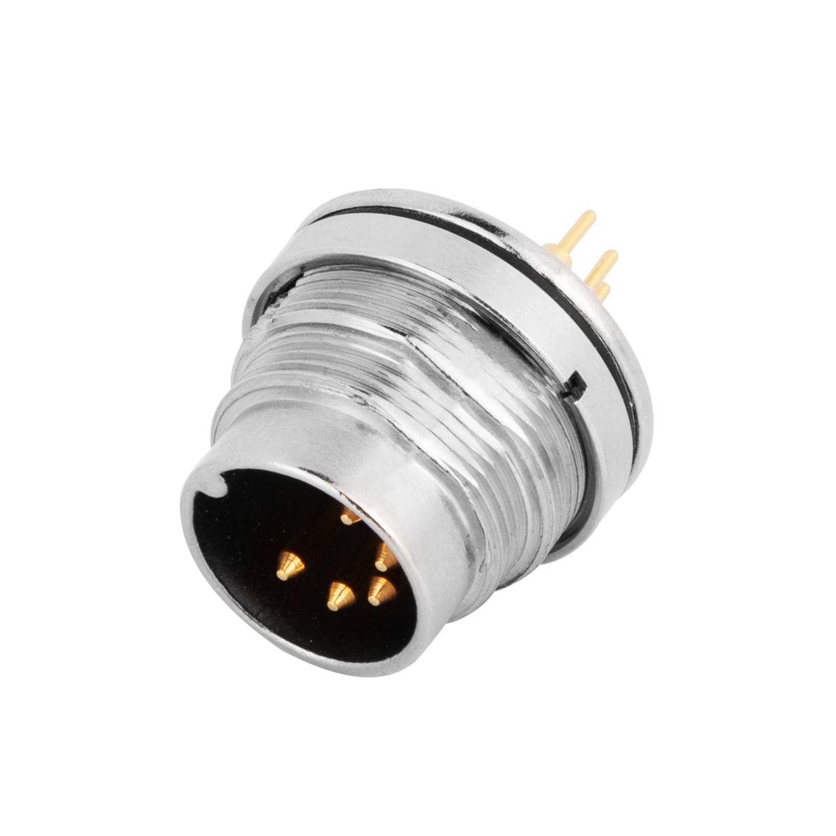
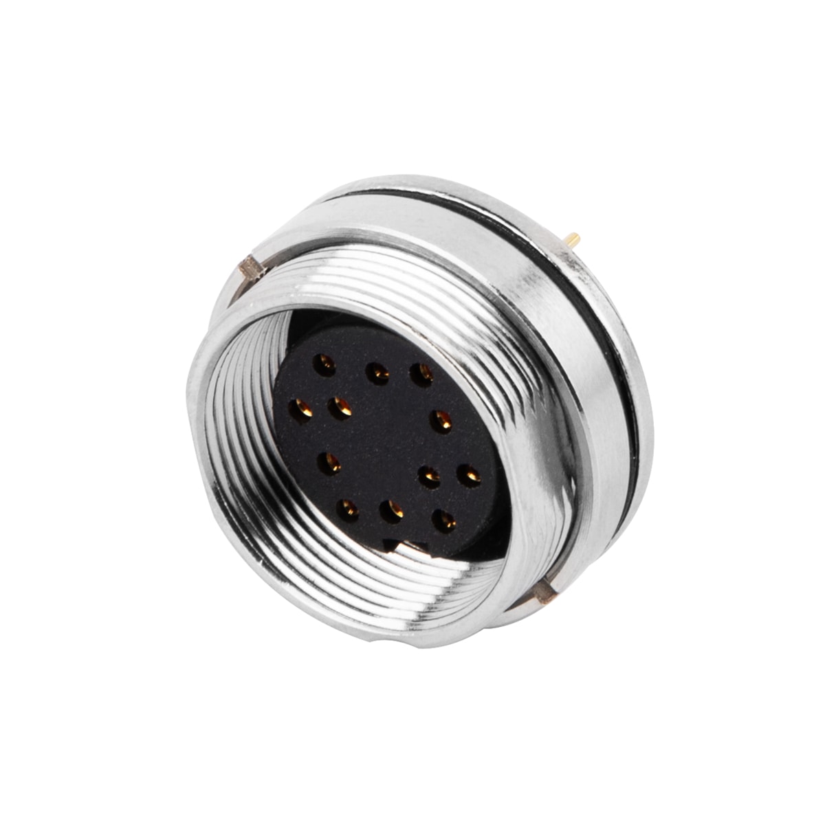
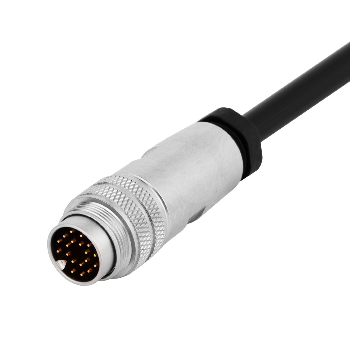
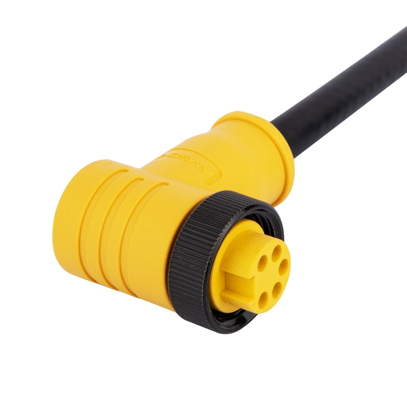
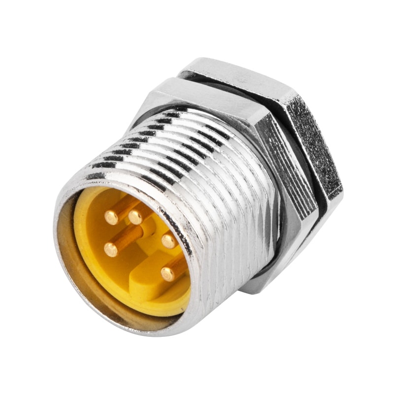
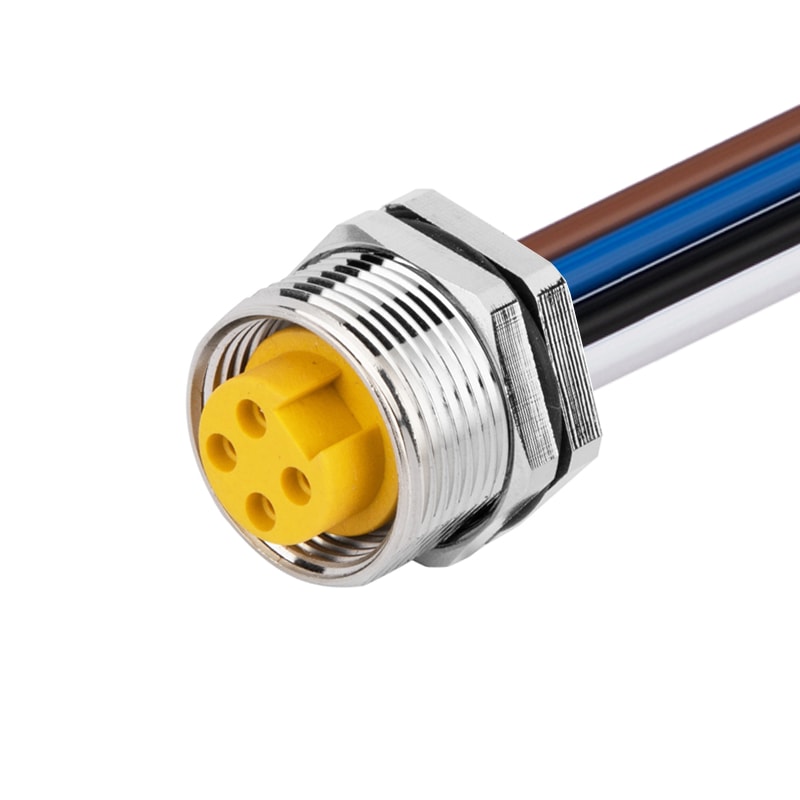
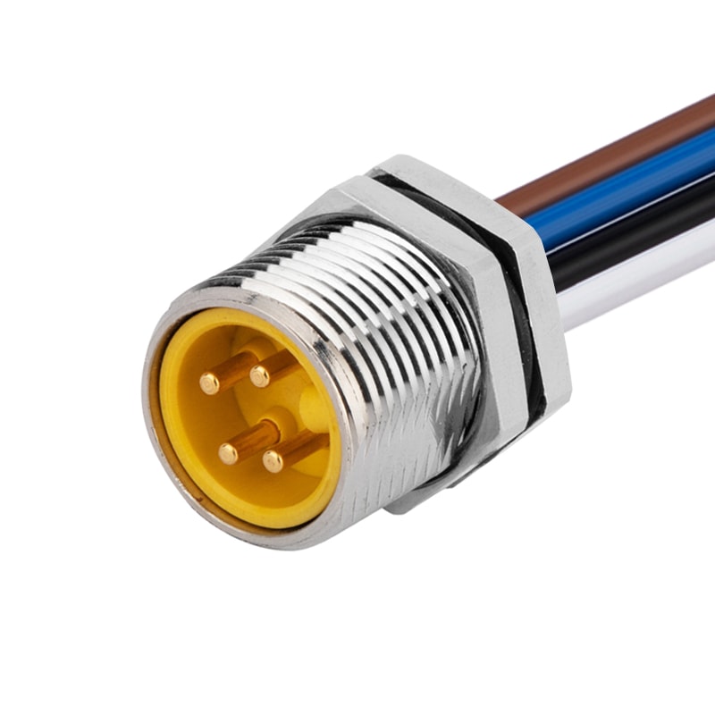
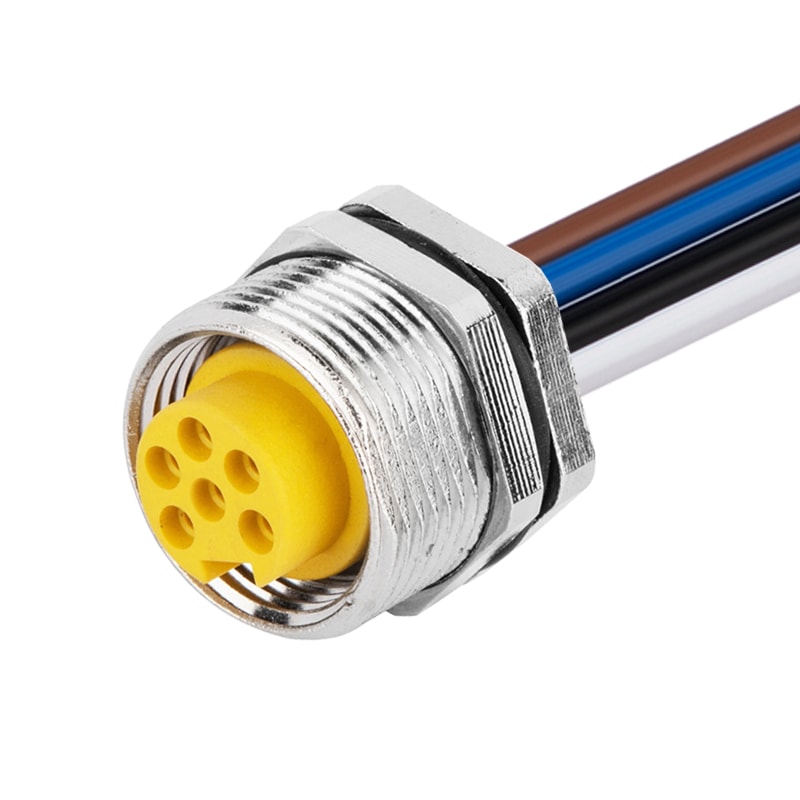
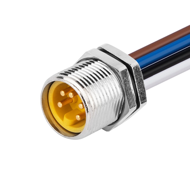
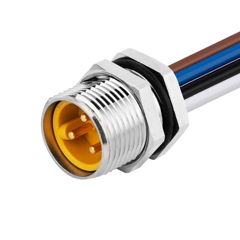
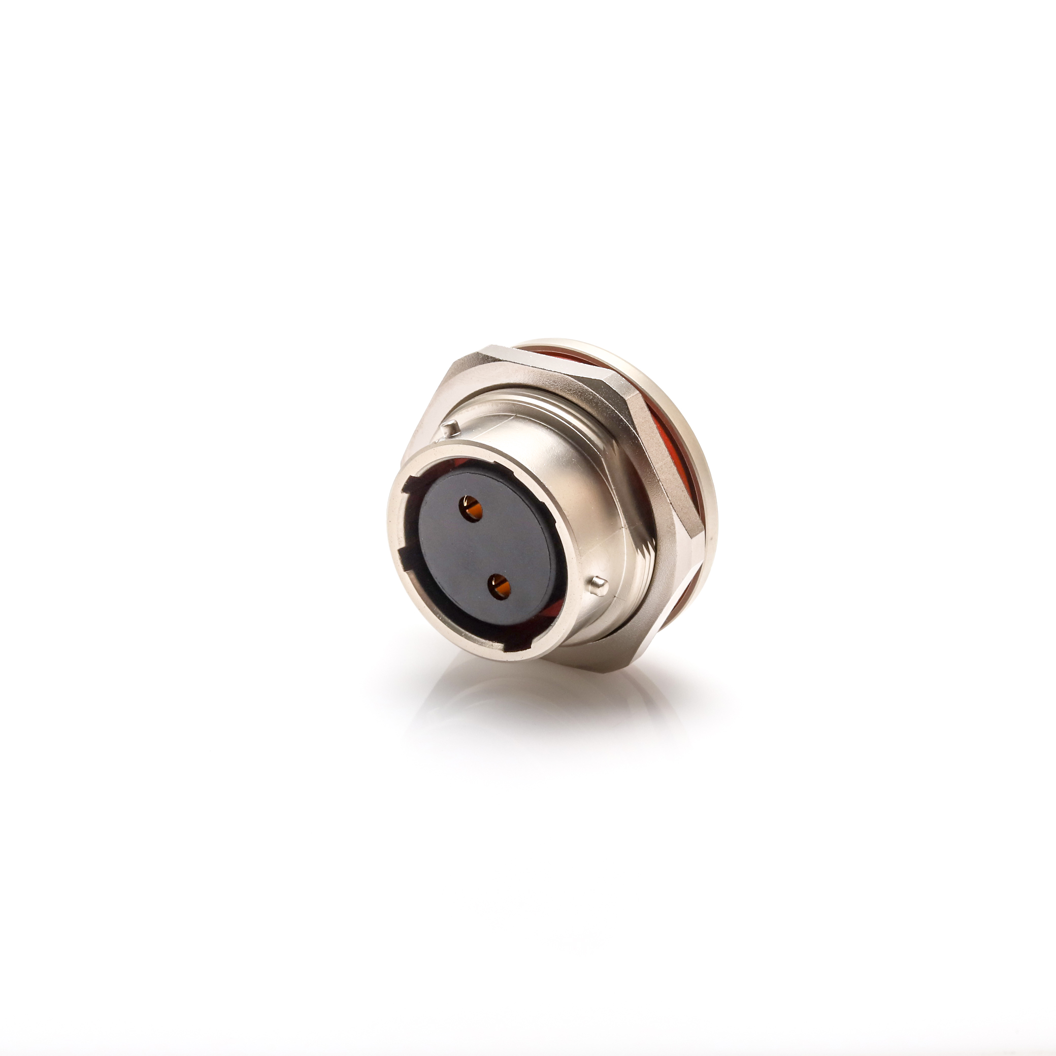
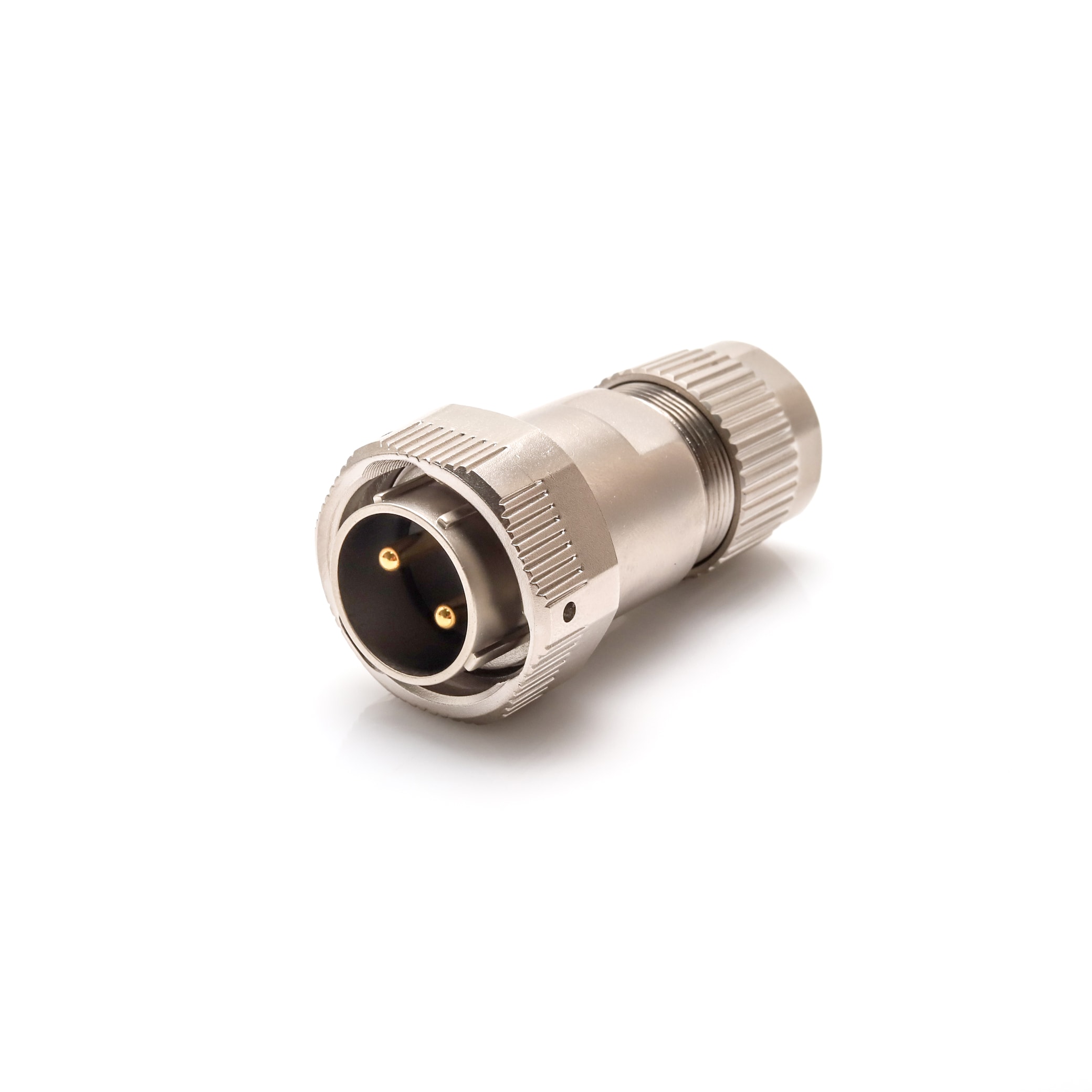
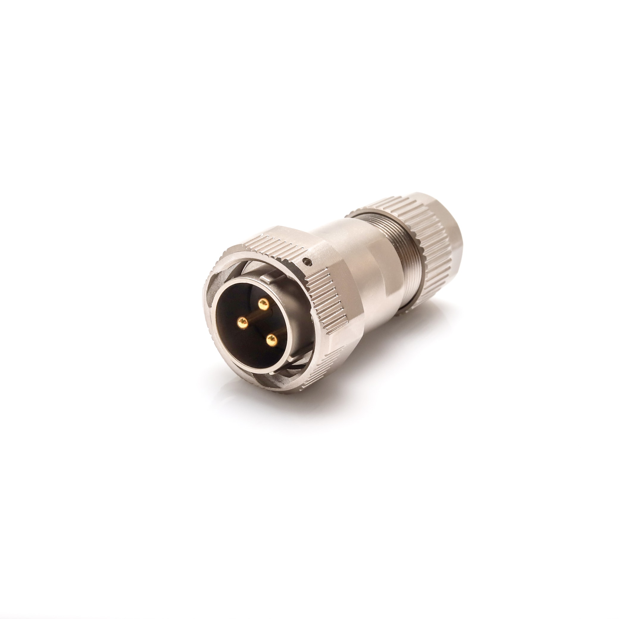
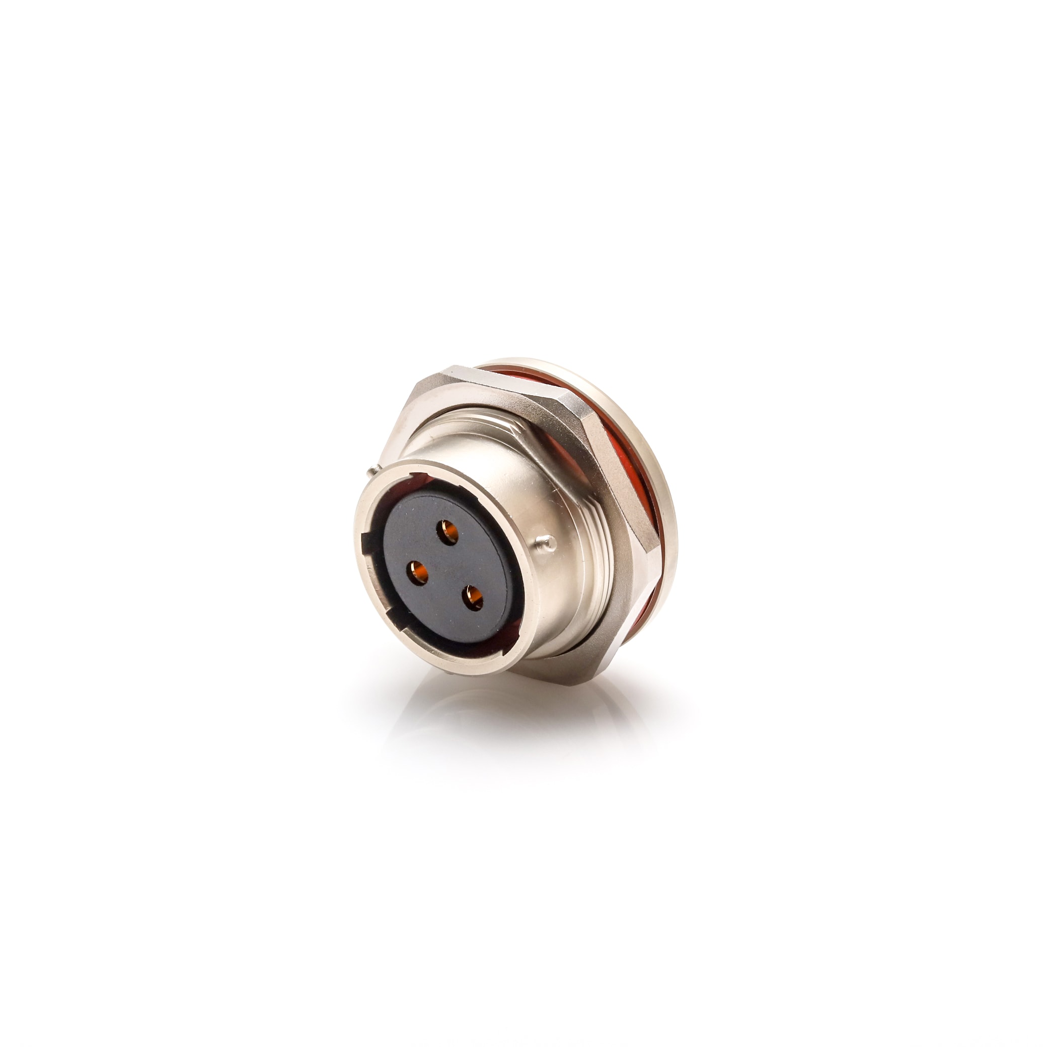
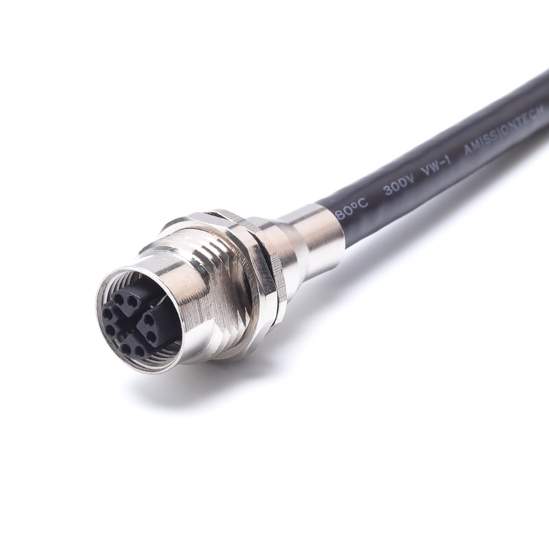
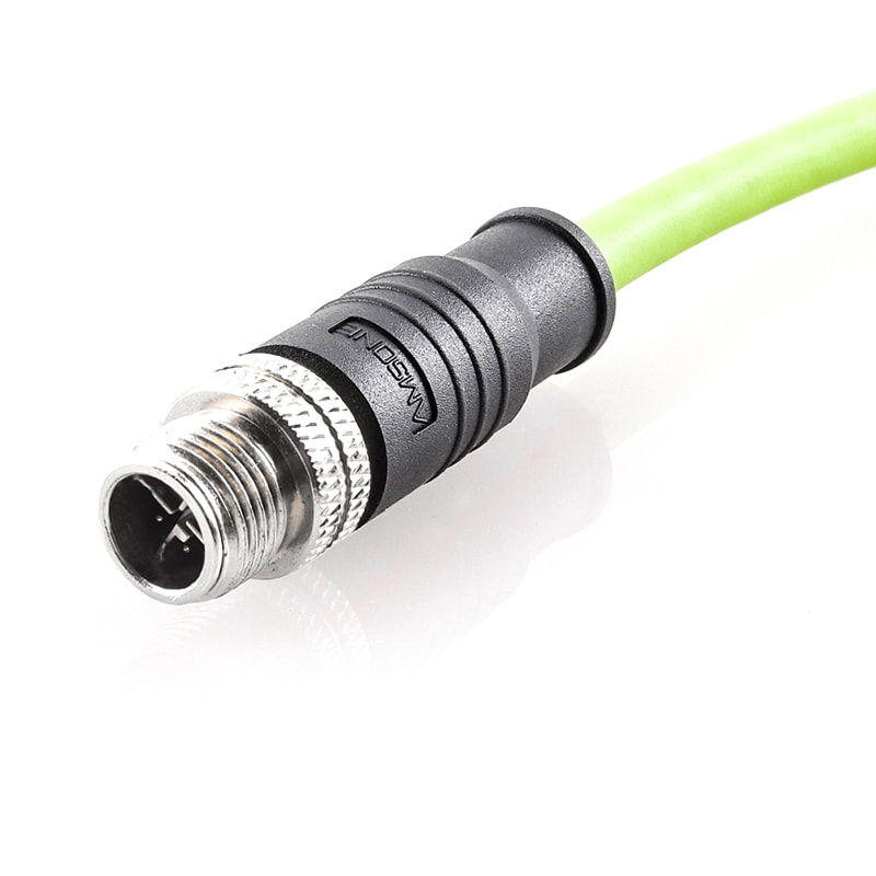
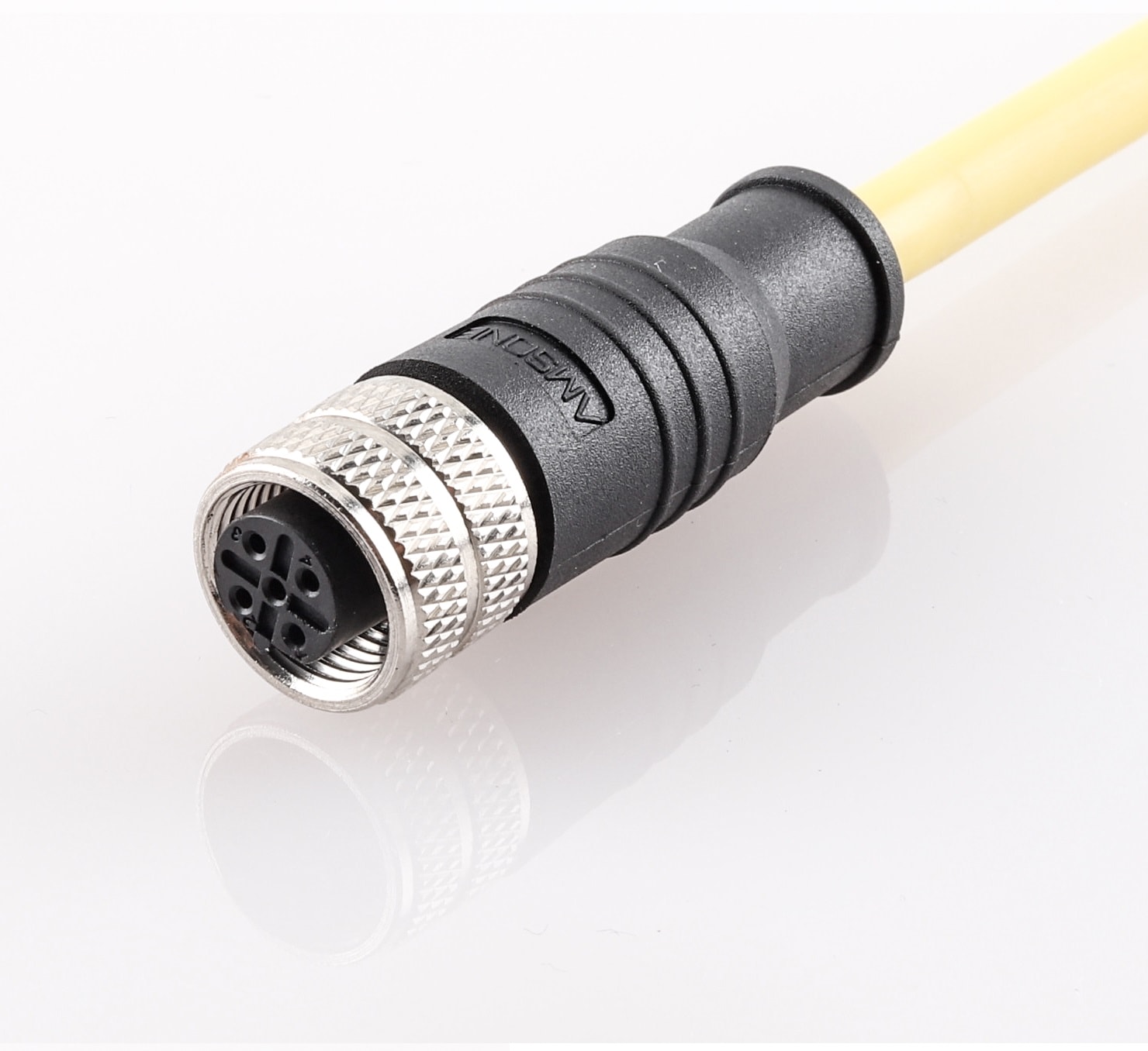
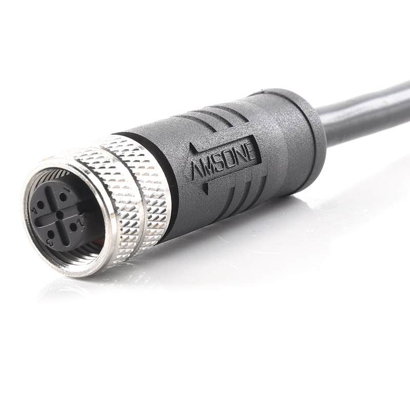
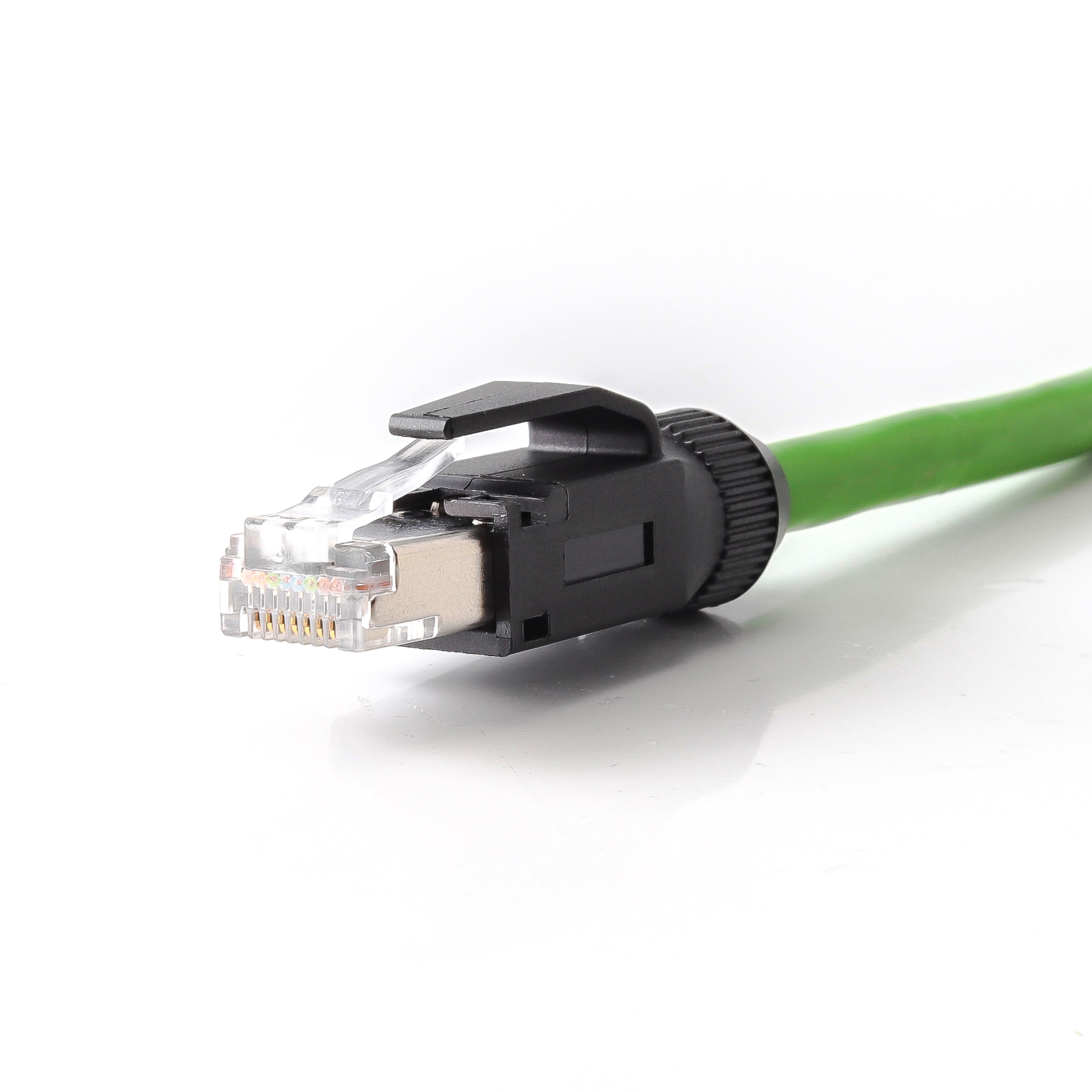
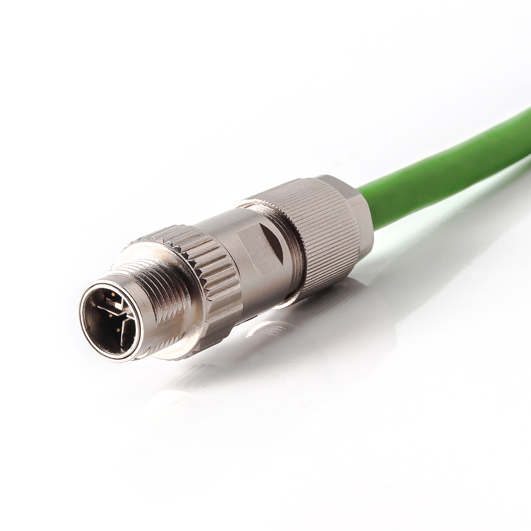
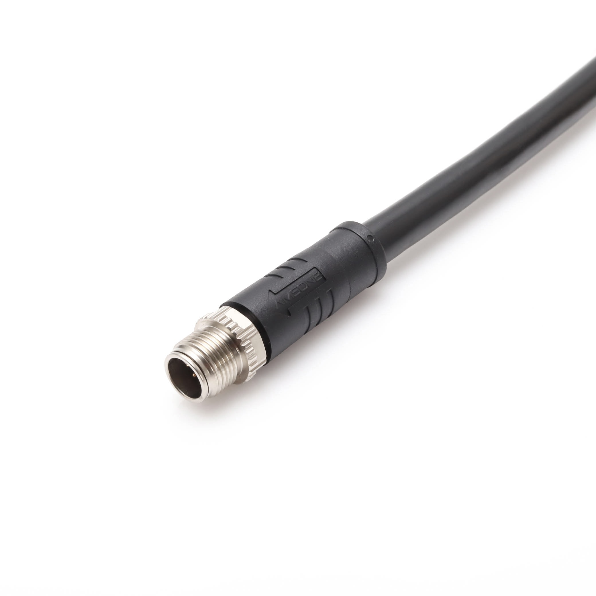
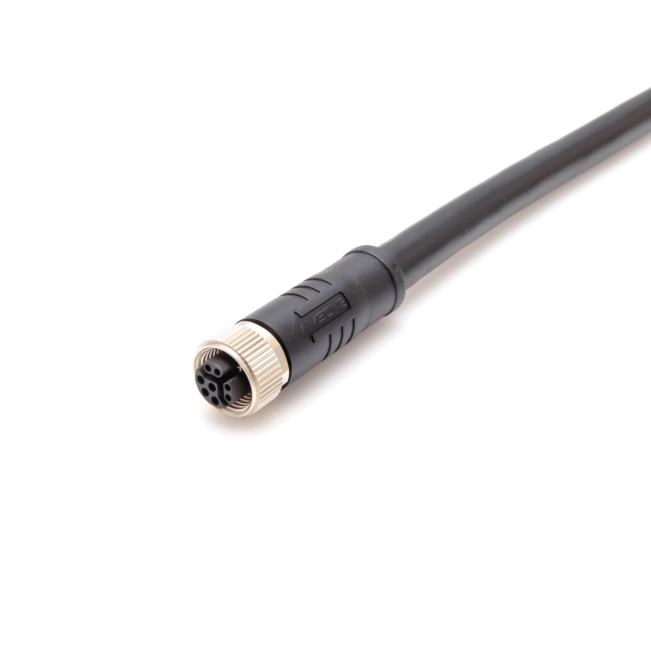
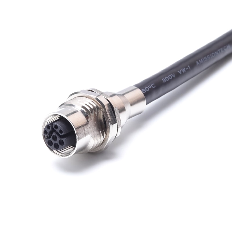
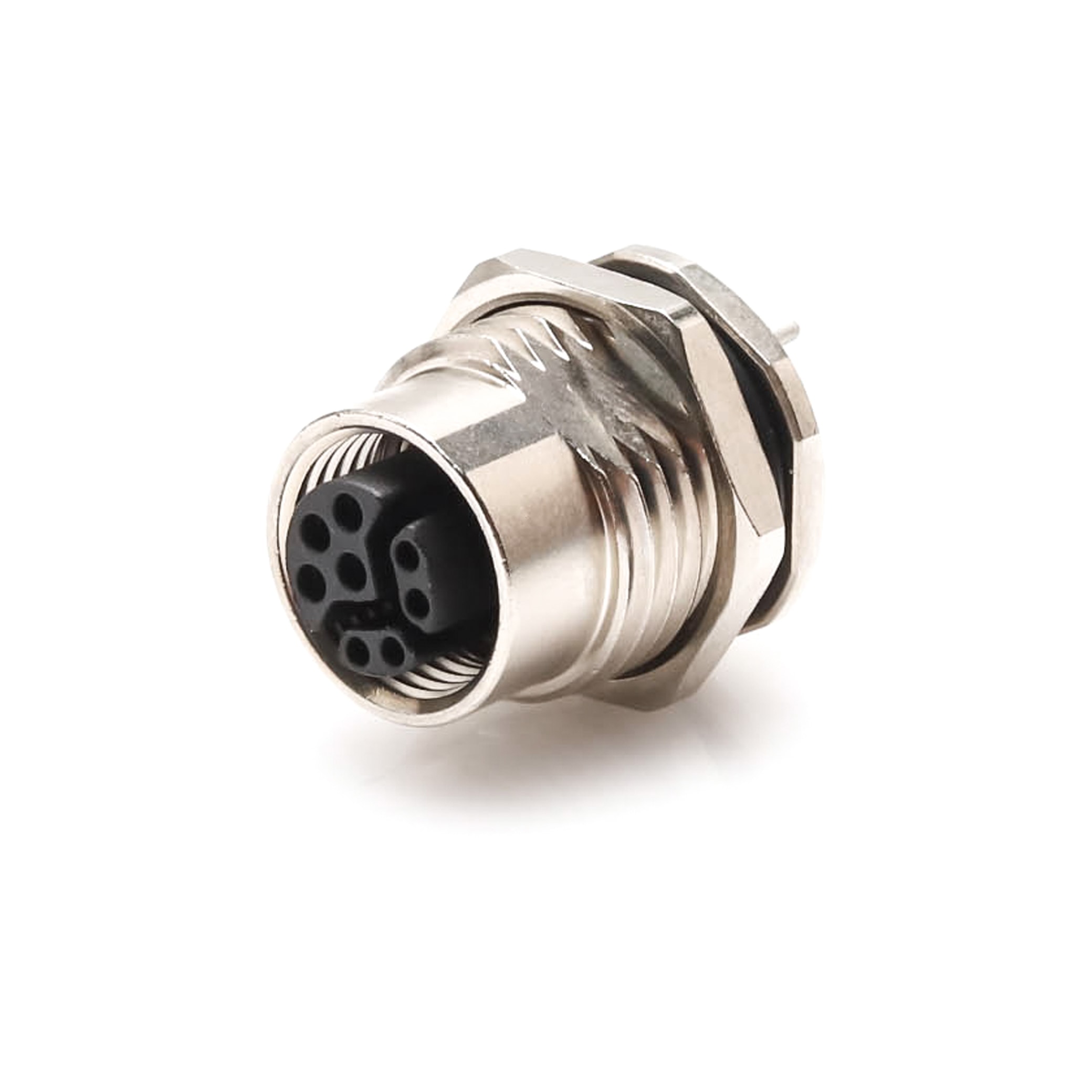
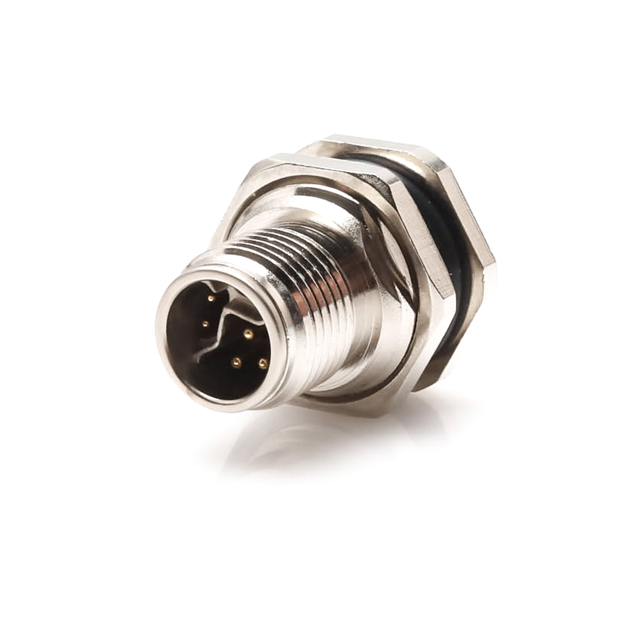
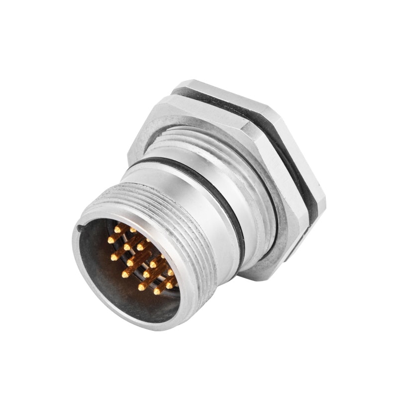
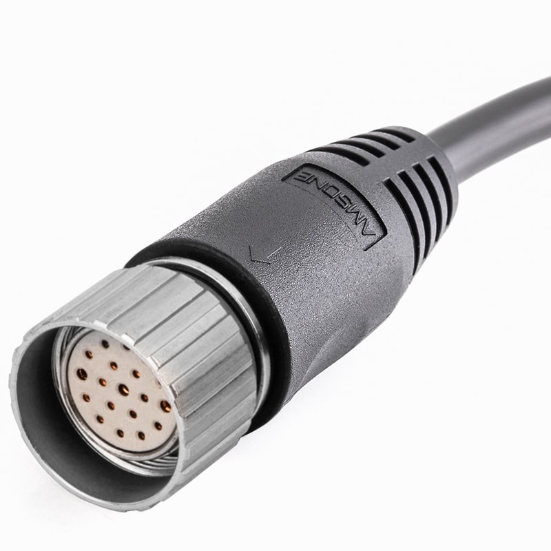
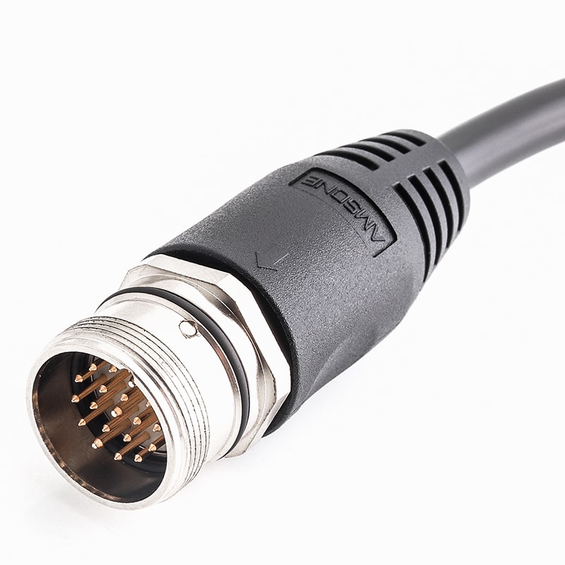
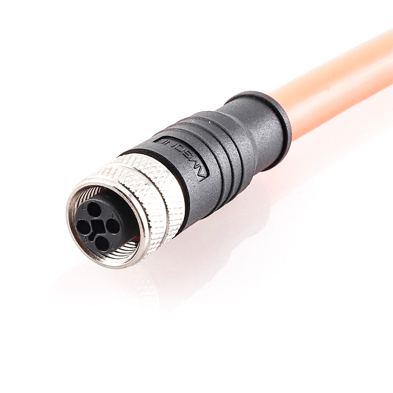
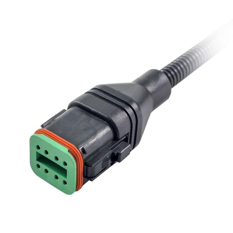
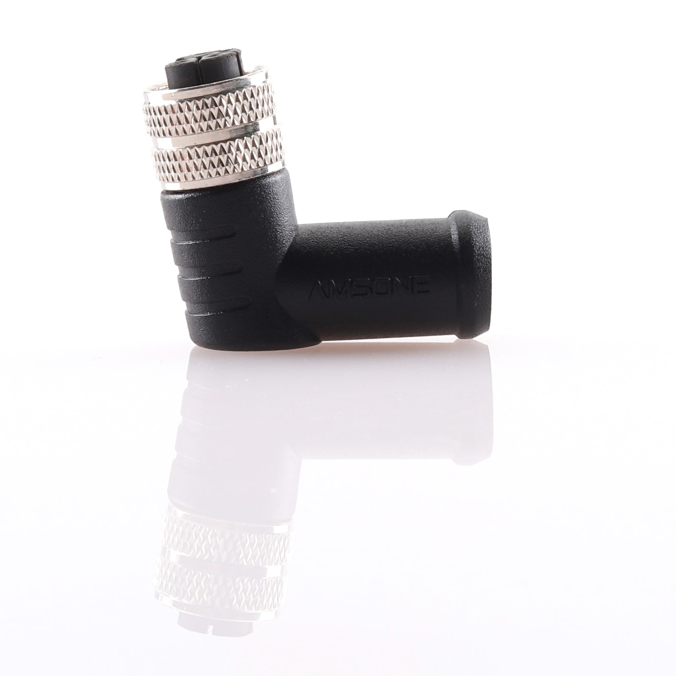
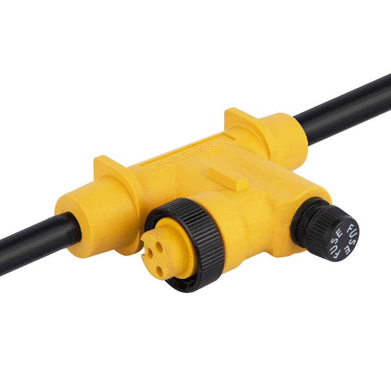
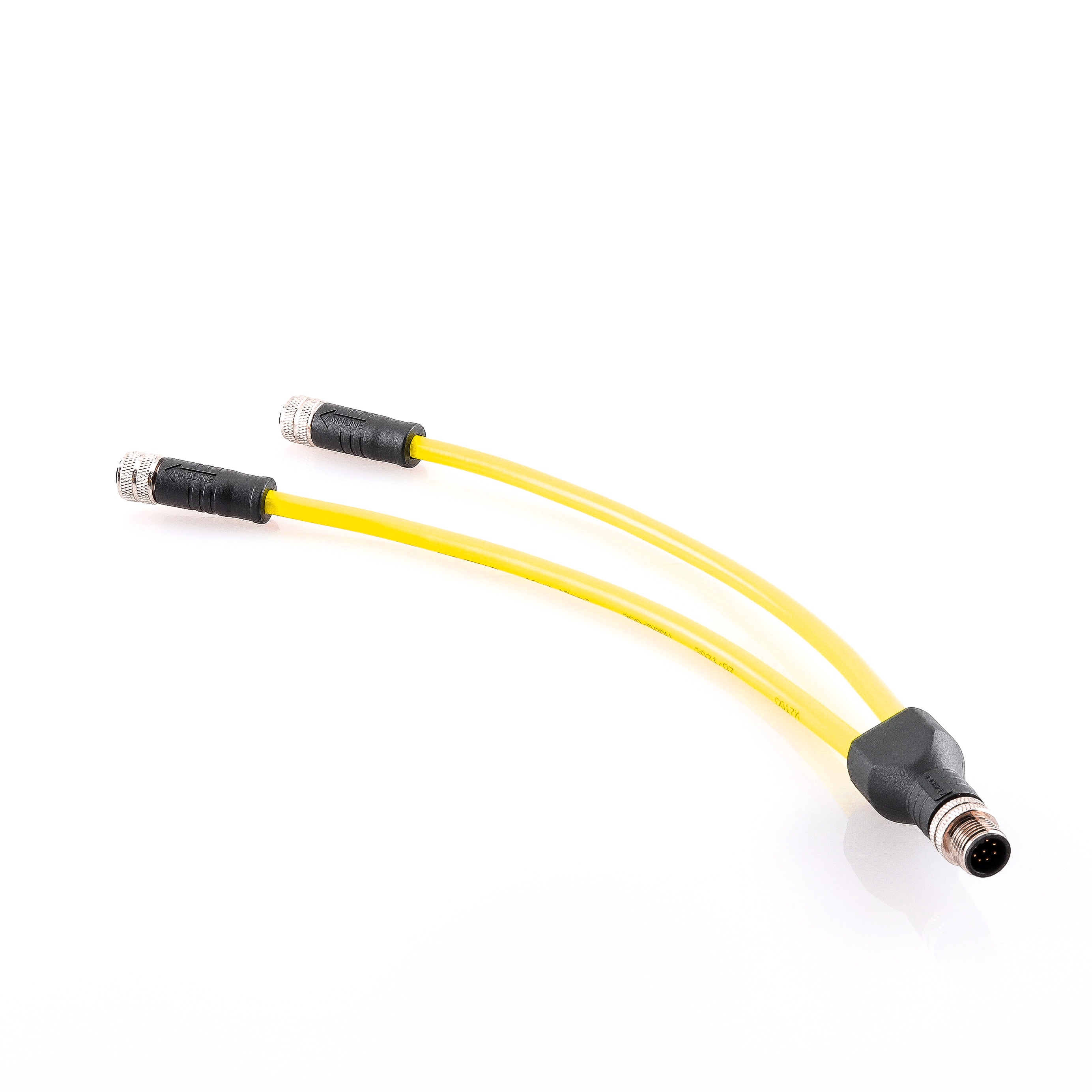
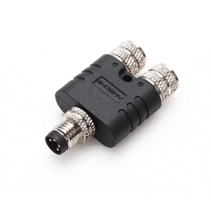
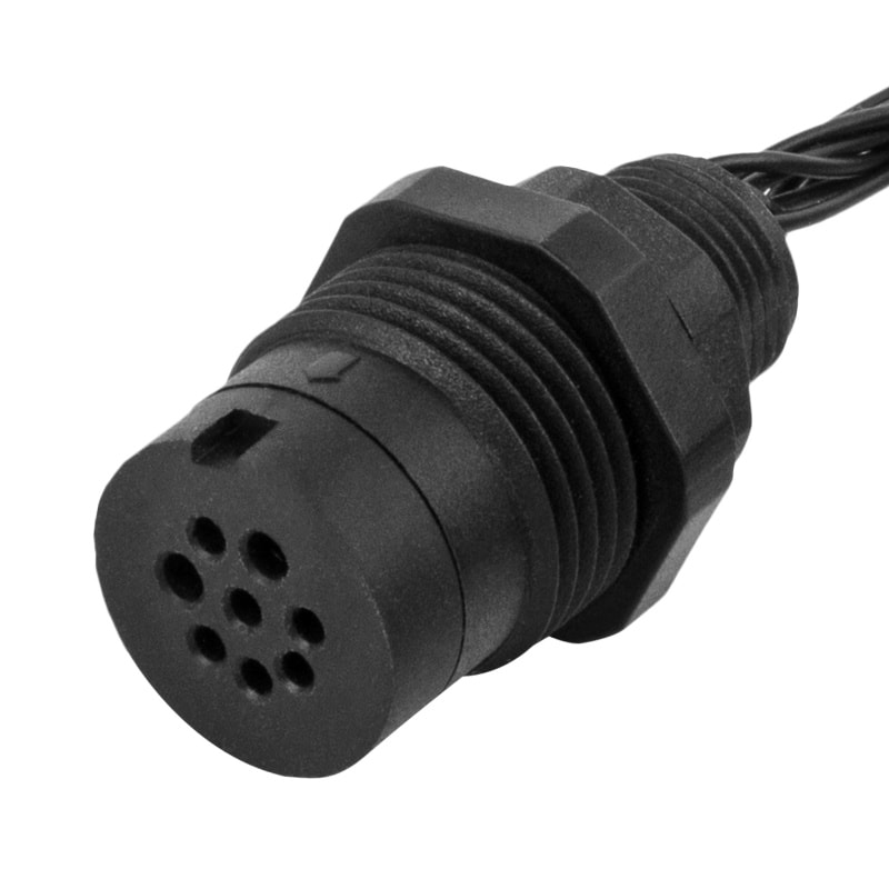
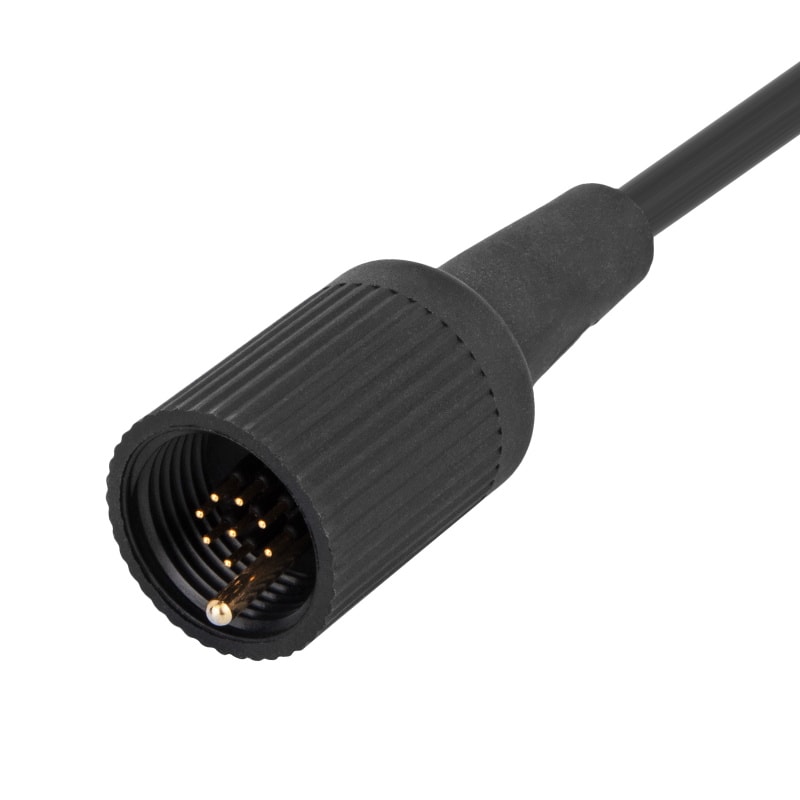
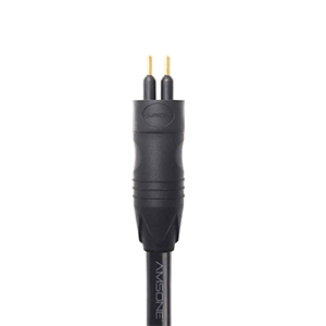
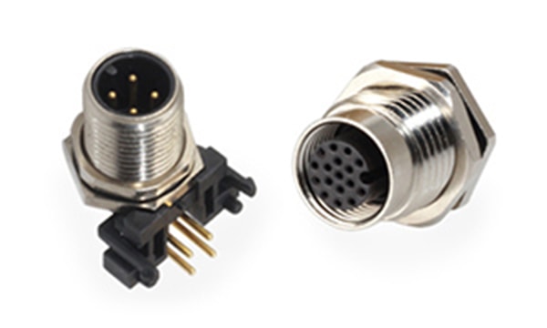
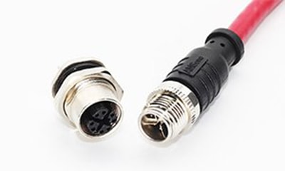
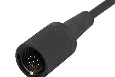
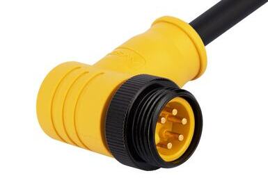
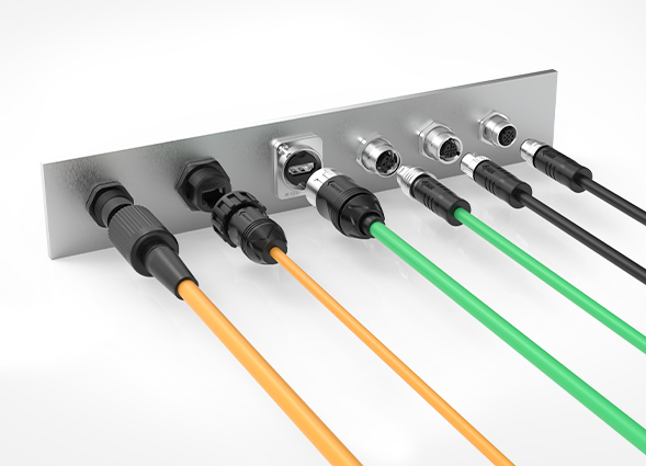
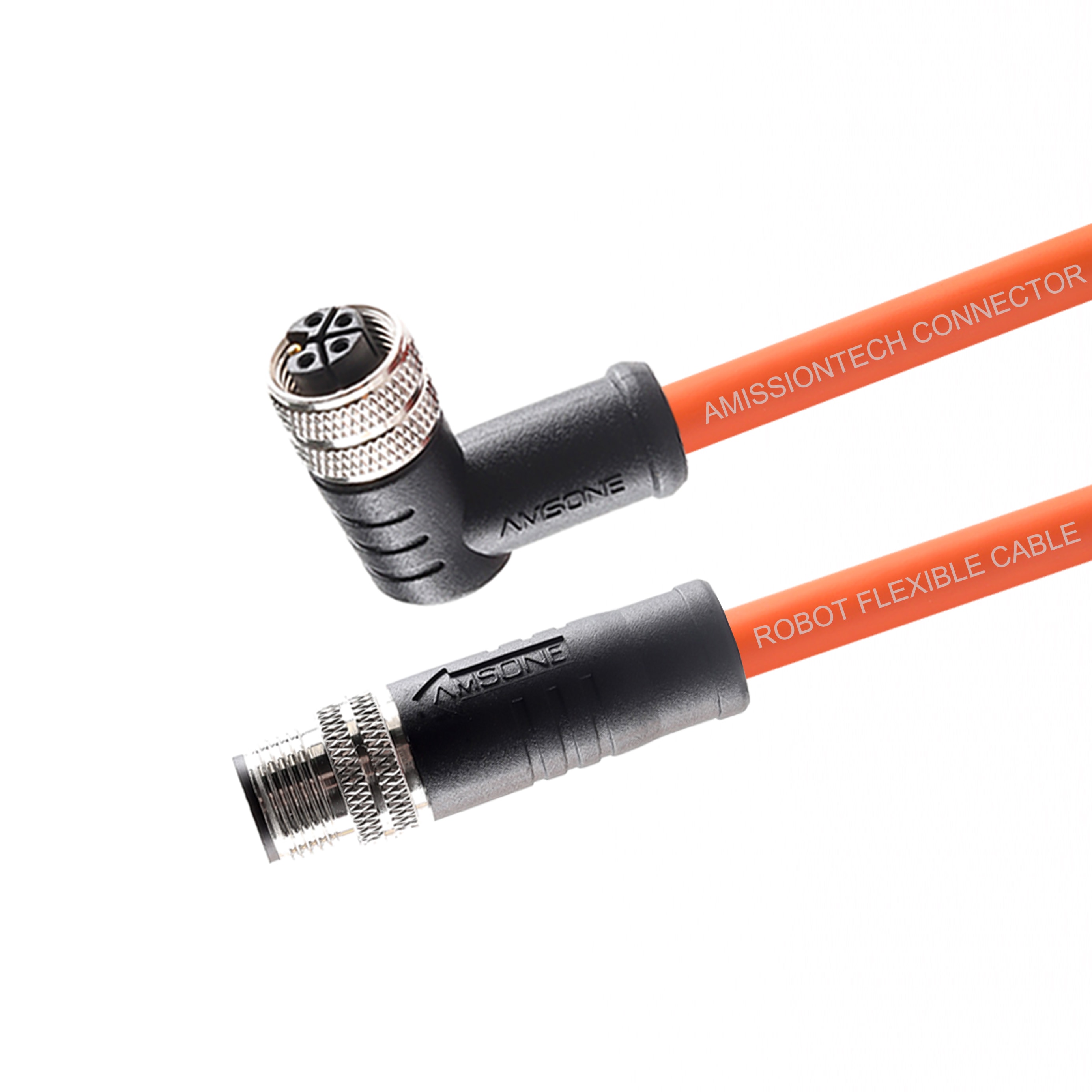
IO-Link connections use standard 3-conductor unshielded cable with M12, M8, or M5 connectors. Maximum cable length is 20 meters between master and device. Each device has a dedicated cable to the master, eliminating bus contention and simplifying fault isolation during troubleshooting.
并排技术比较
|
参数
|
Modbus RTU/TCP
|
IO-Link的
|
|
OSI层
|
Application layer (fieldbus)
|
Physical + data link (device level)
|
|
拓扑
|
Multi-drop bus (RS-485) or star (TCP)
|
点对点
|
|
解决
|
Node address 1-247 (RTU), IP address (TCP)
|
No addressing required
|
|
电缆类型
|
Shielded twisted pair (RS-485) or Ethernet
|
Unshielded 3-conductor (M12)
|
|
最大距离
|
1,200 m (RS-485), 100 m (Ethernet)
|
20 m
|
|
Data Payload
|
16-bit registers, up to 254 bytes/request
|
1-32 bytes cyclic process data
|
|
参数存储
|
Manufacturer-defined register map
|
IODD standardized XML descriptor
|
|
自动配置
|
不可用
|
Master backup and autoload
|
|
诊断
|
CRC + exception codes
|
Health status, counters, event codes
|
|
标准参考
|
Modbus Organization specification
|
IEC 61131-9
|
|
典型设备
|
PLCs, drives, HMIs, energy meters
|
Sensors, actuators, valve manifolds
|
常见问题解答
Can Modbus and IO-Link work together in the same system?
Modbus and IO-Link operate at different layers and can coexist in the same automation architecture. IO-Link masters connect sensors and actuators at the device level and aggregate process data into Modbus TCP registers for transmission to the PLC or SCADA system. This layered approach uses each protocol for its intended purpose.
Which protocol is better for long-distance sensor networks?
Modbus RTU supports cable runs up to 1,200 meters over RS-485, making it suitable for geographically distributed installations such as water treatment plants and pipeline monitoring. IO-Link limits cable length to 20 meters per segment because it targets localized machine-mounted sensor applications within a single equipment cell.
Does IO-Link replace Modbus?
IO-Link does not replace Modbus because each protocol addresses a different architectural layer. Modbus connects controllers and intelligent field devices at the fieldbus level. IO-Link connects individual sensors and actuators to a master gateway at the device level. In a typical installation, IO-Link data from multiple devices is carried to the PLC over Modbus TCP through the master gateway.
How does commissioning time compare between Modbus and IO-Link?
Modbus commissioning requires setting unique node addresses, configuring baud rates and parity settings, mapping register addresses, and testing communication on each slave device. IO-Link commissioning is address-free because the point-to-point topology eliminates node addressing. The IODD file provides plug-and-play device integration through the engineering tool. An IO-Link installation typically commissions in less time than an equivalent Modbus RTU segment.
结语
Modbus and IO-Link are complementary rather than competing protocols. Modbus serves as a fieldbus backbone for controller-to-controller and controller-to-intelligent-device communication with long-distance reach. IO-Link provides a standardized digital interface at the device level with automatic parameter management and rich diagnostic capability.
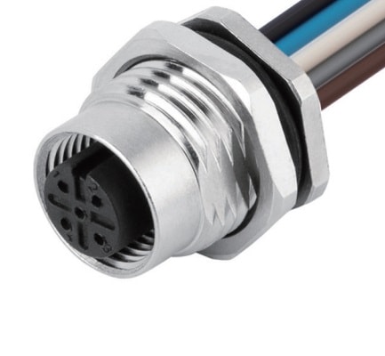
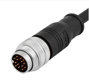
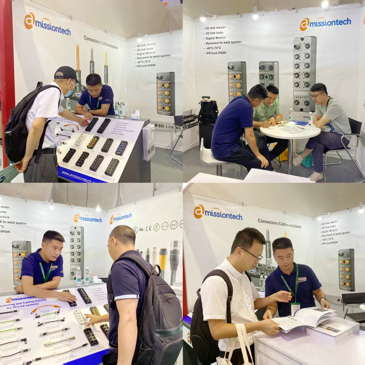
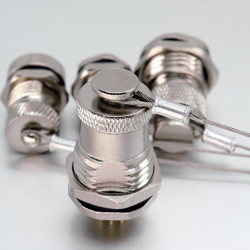
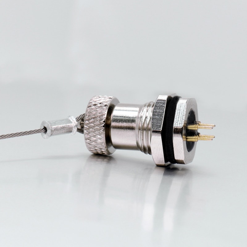
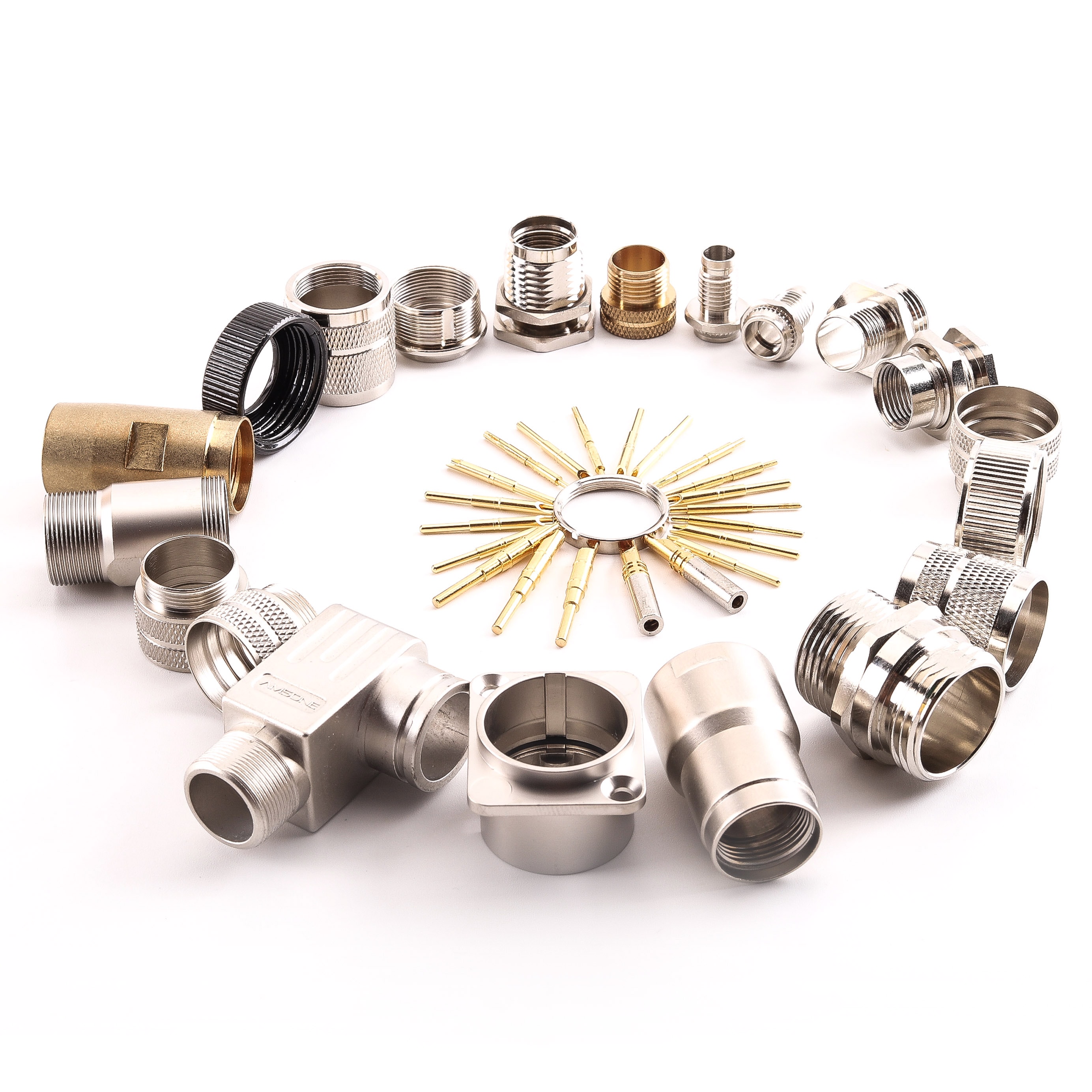
Amissiontech manufactures industrial connectors and cable harnesses with 10-plus years of industry experience, supplying both Modbus-compatible RS-485 connectivity components and IO-Link M12 cable assemblies. Request a Rapid Sourcing Quote from Amissiontech for your protocol-specific connectivity requirements. Contact the Amissiontech Engineering Team for Free Custom Design Support on hybrid wiring solutions.